
Circuit Diagram
Index 835
PDM_KEYER
Published:2009/7/19 22:14:00 Author:Jessie
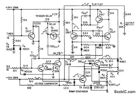
High linearity, low crosstalk and jitter, and high effective input impedance are provided by transistor pulse-duration-modulation keyer. Circuit includes bi-stable flip-flop, linear ramp generator, and voltage comparator. Output pulse widths vary with signal amplitude.-D. A. Williams Jr., Transistors Ruggedize Airborne Telemetry Keyer, Electronics, 31:37, p 81-83. (View)
View full Circuit Diagram | Comments | Reading(1156)
SIMPLE_DUTY_CYCLE_METER
Published:2009/7/10 2:41:00 Author:May

Using an LM317T as a precision clipper, this displays the duty cycle of a pulse train from 0 to 100% on a standard 100-mA analog panel meter. This circuit will work up to about 50 kHz. (View)
View full Circuit Diagram | Comments | Reading(2425)
0_TO__66V_AT_5mA
Published:2009/7/19 22:13:00 Author:Jessie

Voltage follower A2 buffers output that can be adjusted over full range from 0 V to zener limit with R4. Positive supply of A2 must go to voltage slightly more positive than +3 V common if linear output operation is required over full range.-W. G. Jung, IC Op-Amp Cookbook, Howard W. Sams, Indianapolis, IN, 1974, p 159-160. (View)
View full Circuit Diagram | Comments | Reading(518)
QUADRATURE_OUTPUTS_OSCILLATOR
Published:2009/7/10 2:39:00 Author:May

The XR-567 functions as a precision oscillator with two separate square-wave outputs at pins 5 and 8, that are at nearly quadrature phase with each othen. Because of the internal biasing arrangement, the actual phase shift between the two outputs is typically 80%. (View)
View full Circuit Diagram | Comments | Reading(779)
Differential_thermometer
Published:2009/7/19 22:13:00 Author:Jessie

This circuit shows two AD590s and an op amp that is connected to measure temperature differential. The 50-kΩ potentiometer trims offsets in both devices, and can be used to set the size of the difference interval. The circuit can be used for liquid-level detection (if there is a measurable temperature difference in the liquid at different levels). Harris Semiconductors Data Acquisition) 1991 p. 12-9 (View)
View full Circuit Diagram | Comments | Reading(0)
MICROFARAD_COUNTER
Published:2009/7/10 2:39:00 Author:May

This circuit measures capacitance by the time it takes an unknown capacitor to reach 6.32 V (10V×63% or 1 RC time constant) when charged through resistor R. The LED used as a timebase is pulsed by Q3, Q4, and Q5. By counting seconds (two flashes per second) until threshold detector Q1/Q2 stops the count, you can directly read the number of microfarads. R1, R2, R3, R4, and R5 can be any convenient values, such as 1kΩ,10kΩ,100kΩ,1MΩ,10MΩ. (View)
View full Circuit Diagram | Comments | Reading(942)
HIGH_CURRENT_OSCILLATOR
Published:2009/7/10 2:38:00 Author:May

The oscillator output of the XR-567 can be amplified using the output amplifier and high-current logic output available at pin 8. In this manner, the circuit can switch 100-mA load currents without sacrificing oscillator stability. The oscillator frequency can be modulated over ±6% in frequency by applying a control voltage of pin 2. (View)
View full Circuit Diagram | Comments | Reading(2275)
Centigrade_thermometer
Published:2009/7/19 22:13:00 Author:Jessie

This circuit shows an AD590 and a low-current op amp that are connected to form a 0 to 100℃ thermometer. The readout is a 100-μA meter, which is adjusted by the Zero Set and Full-Scale Adjust potentiometer so that 1μA indicates 1℃, 10μA indicates 10℃, and so on. Harris Semiconductor Data Acquisition 1991 p 12-9 (View)
View full Circuit Diagram | Comments | Reading(904)
20_MC_POWER_OSCILLATOR
Published:2009/7/19 22:12:00 Author:Jessie

Colpitts-type common-base circuit gives power output of 500 mw to 50-ohm load, while dissipating 750 mw. –Texas Instruments Inc., “Solid-State Communications,” McGraw-Hill, N. Y., 1966, p 300. (View)
View full Circuit Diagram | Comments | Reading(770)
10_to_150_KHz_OSCILLATOR
Published:2009/7/10 2:38:00 Author:May

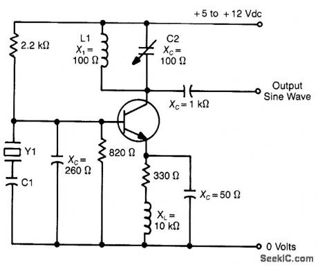
Note:Y1 is H , NT , E cut (View)
View full Circuit Diagram | Comments | Reading(701)
7_23V_AT_12_2A
Published:2009/7/19 22:12:00 Author:Jessie

Ground terminal of LM340T-05 regulator is raised by amount equal to voltage applied to noninverting (+) input of opamp, to give output voltage set by R2 in resistive divider. Short-circuit protection and thermal shutdown are provided overfull output range.- Linear Applications, Vol. 2, National Semiconductor, Santa Clara, CA, 1976, AN-103, p6-7. (View)
View full Circuit Diagram | Comments | Reading(730)
10_MC_CRYSTAL
Published:2009/7/19 22:11:00 Author:Jessie

Collector voltage of transistor is kept low and is stabilized by zener diode D1 in microminiature oscillator using crystal in 10-Mc fundamental mode. Voltage-sensitive capacitor D2 and R7 serve for fine frequency adjustmets.-M. Lysobey, Microminiature Crystal Oscillator Using Wafer Modules, Electronics, 35:15, p 60-61. (View)
View full Circuit Diagram | Comments | Reading(581)
NEARLY_50_DUTY_CYCLE_MULTIVIBRATOR
Published:2009/7/10 2:37:00 Author:May

Three factors contribute to the output symmetry. The capacitor charges and discharges through the same external resistor. An internal resistive divider sets accurate switching thresholds within the chip, the bipolar types use dividers, as well.Most importantly, 101's CMOS output stage switches fully between ground and VCC, avoiding the errors from asymmetry that are often found in a TTL timer's output. The IC's internal switching-threshold tolerances can cause a deviation of several percent from the desired 50% duty cycle. To meet a tighter specification, you might have to select from a group of ICs. (View)
View full Circuit Diagram | Comments | Reading(581)
STABLE_SUBCARRIER_OSCILLATOR
Published:2009/7/19 22:11:00 Author:Jessie

Two Colpitts oscillators, designed for 7,350 cps and 12,300 cps, are used with reactance-type frequency modulation. Input stage of each oscilllator is temperature-stabilized by d-c feedback.-D. Enemark, Balloon-Borne Circuits Sort High-Altitude Cosmic Rays, Electronics, 32:35, p 52:,55.
(View)
View full Circuit Diagram | Comments | Reading(668)
330_MHz_CRYSTAL_OSCILLATOR
Published:2009/7/10 2:37:00 Author:May

A μPC 16516G IC operates in the fundamental mode with an experimental crystal at 330 MHz. The 56-to-270 pF capacitor is not critical; about + 1-dBm RF output is available. (View)
View full Circuit Diagram | Comments | Reading(571)
STABLE_10_KC_COLPITTS
Published:2009/7/19 22:10:00 Author:Jessie

Provides constant-amplitude carrier for data reduction system, at 0.5 V rms with amplitude stability of 0.l% and frequency drift below 0.25% for temperature range of 30 to 50℃.-L. H. Dulberger, Transistor Oscillator Supplies Stable Signal, Electronics, 31:5, p 43. (View)
View full Circuit Diagram | Comments | Reading(671)
SQUARE_WAVE_PULSE_EXTRACTOR
Published:2009/7/10 2:36:00 Author:May

This circuit traps a single positive pulse from a square-wave train. Following the rising edge of an input command, the pulse-out signal emits a replica of one positive pulse of the clock signal simultaneous with the clock signal's next rising edge. The input command signal sets the Q1 output of flip-flop IC1A. Consequently, the next rising edge of the clock signal sets the Q2 output of IC1B, which allows AND gate IC2C to pass the clock signal's next positive pulse. AND gates IC2A and IC2B prevent the generation of brief output glitches by delaying the clock signal by tD seconds (two propa-gation delays). (View)
View full Circuit Diagram | Comments | Reading(837)
Multiplexed_temperature_sensors
Published:2009/7/19 22:10:00 Author:Jessie
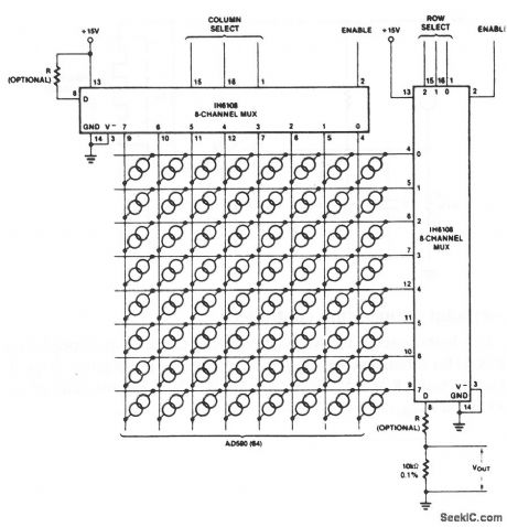
This circuit shows 64 AD590 transducers that are connected as multiplexed temperature sensors. A 6-bit digital word selects one of the 64 sensors (each at a different location, as desired). Harris Semiconductors Data Acquisition 1991 p 12-s (View)
View full Circuit Diagram | Comments | Reading(947)
SIMPLE_WIEN_BRIDGE_OSCILLATOR
Published:2009/7/10 2:35:00 Author:May

In this circuit, the Wien-bridge network provides phase shift, and the lamp regulates the amplitude of the oscillations. The smooth, limiting nature of the lamp's operation, in combination with its simplicity, gives good results. Harmonic distortion is below 0.3% (View)
View full Circuit Diagram | Comments | Reading(1598)
LUNAR__PROBE__TRANSMITTER
Published:2009/7/19 22:10:00 Author:Jessie

Five subcarrier channels are rsed in f-m/p-m systems to transmit ion density, two levels of micrometeorite particle impacts, magnetic field strength, and compartment temperature. Strength, and compartment temperature. Output stage uses four transistors in push-pull parallel to give 400mv output.-R. R. Bennett et al., Circuits for Space Probes, Electronics, 32:25, p 55-57. (View)
View full Circuit Diagram | Comments | Reading(629)
| Pages:835/2234 At 20821822823824825826827828829830831832833834835836837838839840Under 20 |
Circuit Categories
power supply circuit
Amplifier Circuit
Basic Circuit
LED and Light Circuit
Sensor Circuit
Signal Processing
Electrical Equipment Circuit
Control Circuit
Remote Control Circuit
A/D-D/A Converter Circuit
Audio Circuit
Measuring and Test Circuit
Communication Circuit
Computer-Related Circuit
555 Circuit
Automotive Circuit
Repairing Circuit