
Circuit Diagram
Index 833
DIGITAL_TACHOMETER_COUNTER
Published:2009/7/10 3:02:00 Author:May

This circuit produces a readout for the digital tachometer circuit.IC9 is a 3-digit LED display driver,counter,and latch.IC8 drives the common-cathode LEDs,which are enabled by Q1,Q2,and Q3.See page 268,Fig.46-5 for the matching project. (View)
View full Circuit Diagram | Comments | Reading(10492)
60_MW_TRANSMITTER
Published:2009/7/19 22:23:00 Author:Jessie

Amplitude modulation is applied at collector of amplifier-doublet Q4.-H. L. Richter et al., Instrumehting the Explorer I Satellite, Electronics, 32:6, p39-43. (View)
View full Circuit Diagram | Comments | Reading(1008)
CRYSTAL_OSCILLATOR
Published:2009/7/10 3:02:00 Author:May

This simple circuit will oscillate with a wide range of crystals. Connect several different types of cystal holders in parallel to improve versatility. The 3-to 40-pF capacito adjusts crystal frequency over a small range for setting standard-frequency transmissions when the unit is used as a crystal calibrator. (View)
View full Circuit Diagram | Comments | Reading(0)
Transistor_based_thermometer
Published:2009/7/19 22:23:00 Author:Jessie

This circuit provides a 0- to 10-V output, corresponding to a 0 to 100℃ temperature range at the sensor transistor Q2. Accuracy is ±1℃. No calibration is required, and any common small-signal npn can serve as the sensor.The need for calibration is eliminated because Q1 operates as a switched-value current source, alternating between about 10 and 100μA as the LTC1043 commutates switch pins 12 and 14. The two current values are not important, as long as the ratio remains constant. Linear Technology Corporation, 1991 AN45-7 (View)
View full Circuit Diagram | Comments | Reading(802)
F_M_MODULATOR
Published:2009/7/19 22:21:00 Author:Jessie

Provides at leaet 200 kc deviation when applied to base of oscillator transistor, before severe distortion sets in. feedback keeps output impedance low.-D. Enemark, Transistors Improve Telemeter Transmitter, Electronics, 32:11, p 136-137. (View)
View full Circuit Diagram | Comments | Reading(1501)
ECONOMICAL_CRYSTAL_TIME_BASE
Published:2009/7/10 3:01:00 Author:May

The above time base circuit will provide 50-, 100-, or 200-Hz signals from an inexpensive crystal cut for 3.2768MHz, a common crystal used for microprocesser works. It requires a power supply of 5 to 15 V at 0.05 to 2.5 mA. (View)
View full Circuit Diagram | Comments | Reading(1493)
SINGLE_CHIP_CHIME
Published:2009/7/10 3:00:00 Author:May


This circuit uses only one IC, produces a pleasant tone, and sports a single control for adjusting the tone's chiming rate. IC1A and IC1B form an astable multi ibrator, which produces the circuit's basic tone. The multivibrator's frequency is:The component values produce a 668-Hz tone. IC1C buffers the multivibrator's output to the 8- Ω speaker. Current-limiting resistor R2, determines the speaker's volume. R2 minimum value is 220 Ω. IC1D and IC1E form an asymmetric, astable multivibrator, which adds a chime effect to the circuit's basic tone. The chime effect's frequency is:R7 gives this rate multivibrator a slowly varying output signal to produce a pleasant decay for the chime effect. IC1F is an inverting amplifier for the chime multivibrator. (View)
View full Circuit Diagram | Comments | Reading(706)
PPM_DEMAODULATOR
Published:2009/7/19 22:20:00 Author:Jessie
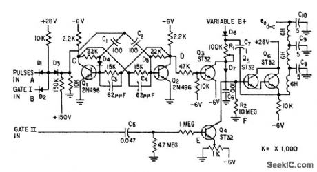
Input is modified two-input semiconductor diode and sate, driving bistable mvbr, modified bootstrap sweep, and filter to give d-c data voltage output.-L. Weisman, Telemetry Demodulator Using Modified And Gate, Electronics, 32:8, p 54-57. (View)
View full Circuit Diagram | Comments | Reading(913)
CRYSTAL-CONTROLLED_BRIDGE_OSCILLATOR
Published:2009/7/10 3:00:00 Author:May

This crystal-controlled oscillator uses the current variations in a small lamp to stabilize amplitude variations. (View)
View full Circuit Diagram | Comments | Reading(591)
RS_232_port_with_four_pairs_of_inputs_outputs
Published:2009/7/19 22:20:00 Author:Jessie

This circuit shows two ICL232s that are combined to accommodate four pairs of inputs/outputs. Notice that each circuit requires two charge-pump capacitors C1/C2, but can share common reservoir capacitors C3/C4. Harris Semiconductors, Data Acquisition 1991 p 137. (View)
View full Circuit Diagram | Comments | Reading(549)
PHASE_LOCKED_20_MHz_OSCILLATOR
Published:2009/7/10 2:59:00 Author:May

This circuit produces a 20-MHz clock phase locked to a 10-MHz dock present in the Apple MAC II.To generate the 20-MHz signal, the circuit produces a 25 ns negative-going pulse delayed 50 ns from the falling edge of the 10-MHz Nubus clock input at point E. NORing that pulse with the Nubus clock produces the 20-MHz clock at point G. Applying the 25-ms pulse to the set input of an S/R flip-flop and the Nubus clock to the reset input results in a 10-MHz square wave at F. (View)
View full Circuit Diagram | Comments | Reading(1328)
100_MC_LINK_TRANSMITTER
Published:2009/7/19 22:19:00 Author:Jessie
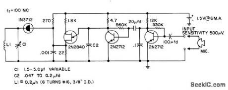
Signal picked up by microphone is amplified by first 2N2712, which turns off second 2N2712, allowing C1 to charge up and ire 2N2840 unijunction oscillator, producing pulse that modulates tunnel-diode transmitter.- Transistor Manual, Seventh Edition, General Electric Co., 1964, p 362. (View)
View full Circuit Diagram | Comments | Reading(1657)
SIMPLE_ELECTROMETER
Published:2009/7/10 2:59:00 Author:May

This electrometer is useful as a relative indicator of static charges or as an electric fteld in a chargefree environmen.An induced negative charge on the probe will reduce drain current toward zero. (View)
View full Circuit Diagram | Comments | Reading(1514)
Simple_duplex_RS_232_port
Published:2009/7/19 22:19:00 Author:Jessie

This circuit shows an ICL232 that is connected as a simple duplex RS-232 port with CTS/RTS handshaking. Fixed output signals, such as DTR (data terminal ready) and DSRS (data signaling rate select), are generated by driving them through a 5-kΩ resistor that is connected to V+. Harris Semiconductor. Data Acquisition 1991 p 136 (View)
View full Circuit Diagram | Comments | Reading(1468)
1_to_20_MHz_TTL_OSCILLATOR
Published:2009/7/10 2:59:00 Author:May

View full Circuit Diagram | Comments | Reading(673)
LCD_interface_using_an_ICM7217A_a_DF411_and_a_CD4011
Published:2009/7/19 22:19:00 Author:Jessie

LCD interface using an ICM7217A, a DF411 and a CD4011.Total system power consumption is less than 5 mW, Common-cathode devices should be used since the digit drivers are CMOS, while in common-anode devices the digit drivers are NPN devices and will not provide full logic swing (courtesy Intersil, Inc.). (View)
View full Circuit Diagram | Comments | Reading(846)
DIGITAL_VOM_PHASE_METER
Published:2009/7/10 2:52:00 Author:May

The phase-angle meter will work with either analog or digital inputs.A DVM is used as a readoutdevice.The output is 1mV per degree(360mV or degrees full-scale),The MC1404 precision regulator maintains calibration with a battery source(9V). (View)
View full Circuit Diagram | Comments | Reading(3990)
CRYSTAL_MOS_FET
Published:2009/7/19 22:19:00 Author:Jessie

Oscillation is maintained even with 100-microvolt oscillator output signal when using mos fet.-G. G. Luettgenau and S. H. Barnes, Designing With Low-Noise MOS FETs: A Little Different But No Harder, Electronics, 37:31, p 53-58. (View)
View full Circuit Diagram | Comments | Reading(735)
Simple_thermometer
Published:2009/7/19 22:19:00 Author:Jessie

With the connections as shown, the meter displays directly current output in degrees Kelvin. Using the AD590J, the sensor output is within ±10° over the entire range. Harris Semiconductors. Data Acquisition 1991 p. 12-10 (View)
View full Circuit Diagram | Comments | Reading(579)
TWO_FREQUENCY_COLPITTS_OSCILLATOR
Published:2009/7/10 2:49:00 Author:May

Using switched crystals, this oscillator is intended for receiver alignment purposes. (View)
View full Circuit Diagram | Comments | Reading(702)
| Pages:833/2234 At 20821822823824825826827828829830831832833834835836837838839840Under 20 |
Circuit Categories
power supply circuit
Amplifier Circuit
Basic Circuit
LED and Light Circuit
Sensor Circuit
Signal Processing
Electrical Equipment Circuit
Control Circuit
Remote Control Circuit
A/D-D/A Converter Circuit
Audio Circuit
Measuring and Test Circuit
Communication Circuit
Computer-Related Circuit
555 Circuit
Automotive Circuit
Repairing Circuit