
Circuit Diagram
Index 823
AIR_PRESSURE_CHANGE_DETECTOR
Published:2009/7/10 4:15:00 Author:May

A piezoelectric detector (BZ1) is used in this circuit to detect a change in air pressure. BZ1 produces a voltage that is amplified by U1A and UlB. Frequency response is limited to low frequencies. The signal is rectified by D1 and D2 and drives Q1, which activates BZ2, a piezoelectric buzzer. (View)
View full Circuit Diagram | Comments | Reading(863)
SENSITIVE_CONTINUITY_CHECKER
Published:2009/7/10 4:14:00 Author:May

This continuity checker (built around an LM339 quad comparator with open-collector outputs) elimi-nates false readings because of coils or low-resistance devices in a circuit.
U1 is a comparator that acts as a sensing amplifier for the bridge circuit (R1 and D1, R3 and the unknown resistance, RX that is connected across the test leads. When RX is less than this predetermined value (by the setting of R1), the LED lights and BZ1 sounds. (View)
View full Circuit Diagram | Comments | Reading(606)
SQUARE_WAVE_ASTABLE_CIRCUIT
Published:2009/7/10 4:12:00 Author:May

This 555 circuit produces a square wave. The frequency depends on the values of RT and CT, as per the design equations. (View)
View full Circuit Diagram | Comments | Reading(489)
Precision_electronic_thermometer
Published:2009/7/19 21:38:00 Author:Jessie


This circuit shows how a voltage reference can be combined with an op amp to create an electronic thermometer (with±5% accuracy). To calibrate, measure the voltage at pin 3 of REF-02, and the ambient room temperature (TA in℃). Then find X as follows:
selected from table in Fig. 12-8. Then, turn off the power, short pin 6 (VO) of REF-02 to ground, apply exactly 100.00 mV to the op-amp output (pin 6 of OP-07), and adjust RB2 so that VB= X. Now, remove the short and the 100-mV source, reapply circuit power, and adjust RP so that the op-amp output voltage equals (TA) (,S). The system is now calibrated. For remote sensor applications, a 1.5-kΩ resistor (RS) must be connected in series with pin 6 of REF-02. This isolates REF-02 from cable capacitances. Use low temperature coefficient metal-film resistors for RA, RB, and RC Raytheon Linear integrated Circuits, 1989 p. 8-16 (View)
View full Circuit Diagram | Comments | Reading(615)
Inverting_unity_gain_high_slew_rate_circuit_using_an_ECG915_operational_amplifier_
Published:2009/7/19 21:38:00 Author:Jessie

Inverting unity-gain high-slew-rate circuit using an ECG915 operational amplifier (courtesy GTE Sylvania Incorporated). (View)
View full Circuit Diagram | Comments | Reading(545)
FOLDBACK_CURRENT_LIMITING
Published:2009/7/19 21:38:00 Author:Jessie

Reduces short-circuit output current of National LM125 dual tracking regulator sections to fraction of full-load output current, avoiding need for larger heatsink. Programmable current source is used to give constant voltage drop across R5 for negative regulator. Simple resistor divider serves same purpose for positive regulator. Design examples are given.-T. Smathers and N. Sevastopoulos, LM125/LM126/LM127 Precision Dual Tracking Regulators, National Semi-conductor, Santa Clara, CA, 1974, AN-82, p7. (View)
View full Circuit Diagram | Comments | Reading(1057)
PEAK_DETECTOR_1
Published:2009/7/10 4:12:00 Author:May

An analog signal requires about 100 ns to prop-OUTPUT agate through the HA-5320. For time-varying signals, this assures a voltage difference between input and output. Also, the voltage changes polarity when the signal slope changes polarity (passes a peak). This behavior makes the circuit a possible sample/hold peak detector, by adding a comparator to detect the polarity changes.
The exclusive NOR gate allows a reset function which forces the HA-5320 to the sample mode. The connections shown detect positive peaks; the comparator inputs can be reversed to detect negative peaks. Also, the offset must be introduced to provide enough step in voltage to trip the comparator after passing a peak. This circuit works well from below 100 Hz up to the frequency at which slew-rate limiting occurs. It captures the amplitude of voltage pulses, provided that the pulse duration is sufftcient to slew to the top of the pulse. (View)
View full Circuit Diagram | Comments | Reading(960)
JFET_WITH_AC_COUPLING
Published:2009/7/10 4:11:00 Author:May

Connection shown gives very high voltage gain. Use of C1 as Miller integrator or capacitance multiplier allows simple circuit to handle very long time constant.- FET Databook, National Semiconductor, Santa Clara, CA, 1977, p 6-26-6-36. (View)
View full Circuit Diagram | Comments | Reading(651)
HIGH_GAIN_CURRENT_SENSOR
Published:2009/7/10 4:11:00 Author:May
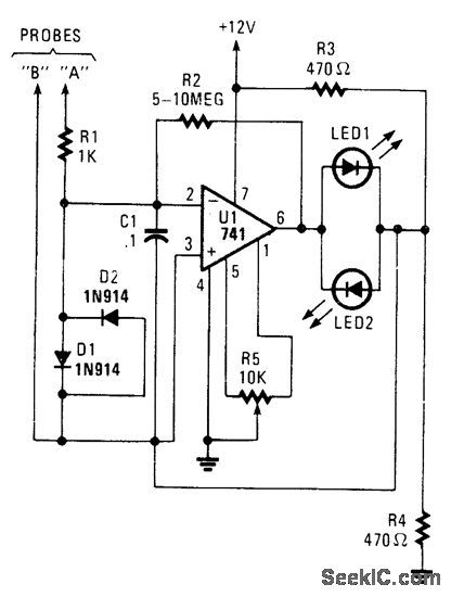
A high-gain amplifter using a UA741 is used to sense relative voltage drop in a conductor, and therefore current in the conductor. R2 can be increased to 10 MΩ for increased sensitivity. LEDt and LED2 provide polarity indication. This circuit can be used to detect current flowing in a PC board trace, and also for locating shorts and opens. (View)
View full Circuit Diagram | Comments | Reading(1442)
12_22_Mc_VOLTAGE_CONTROLLED_OSCILLA_TOR
Published:2009/7/19 21:38:00 Author:Jessie

Voltage-variable capacitor tunes tunnel-diode oscillator electronically.- Transistor Manual, Seventh Edition, General Electric Co., 1964, p 350. (View)
View full Circuit Diagram | Comments | Reading(656)
Noninverting_op_amp_using_an_AD510_8_pin_TO99_
Published:2009/7/19 21:38:00 Author:Jessie

Noninverting op amp using an AD510 8-pin TO99 (courtesy Analog Devices, Inc.). (View)
View full Circuit Diagram | Comments | Reading(506)
MECHANICAL_COUNTER_DRIVE
Published:2009/7/19 21:37:00 Author:Jessie

Takes output from scale-of-64 circuit and converts to 40-millisec square-wave pulse by means of complementary mvbr, to drive coil of mechanical register, once for every 64 pulses from G –M tube,-F, E. Armstrong, Battery Powered Portable scaler Electronic, 33:19 74-75. (View)
View full Circuit Diagram | Comments | Reading(510)
Inverting_amplifier_using_half_of_an_ECG947_dual_operational_amplifier
Published:2009/7/19 21:37:00 Author:Jessie

Inverting amplifier using half of an ECG947 dual operational amplifier. The ECG947 is short-circuit protected and requires no external components for frequency compensation (courtesy GTE Sylvania Incorporated). (View)
View full Circuit Diagram | Comments | Reading(516)
3_260_MC_TUNNEL_DIODE_OSCILLATOR
Published:2009/7/19 21:37:00 Author:Jessie

Uses plug-in coils to generate sine-wave output over wide frequency range.- Transistor Manual, Seventh Edition, General Electric Co., 1964, p 352. (View)
View full Circuit Diagram | Comments | Reading(662)
Op_amp_in_closed_loop_frequency_compensated_configuration_
Published:2009/7/19 21:36:00 Author:Jessie

Op amp in closed-loop frequency-compensated configuration (courtesy Motorola Semiconductor Products Inc.). (View)
View full Circuit Diagram | Comments | Reading(583)
±15V_TRACKING
Published:2009/7/19 21:36:00 Author:Jessie

Single NE/SE5554 dual tracking regulator is used with pass transistors to give higher output current than 200-mA limit for each section of regulator, with close-tolerance tracking.- Signetics Analog Data Manual, Signetics, Sunnyvale, CA, 1977, p 672-673. (View)
View full Circuit Diagram | Comments | Reading(1429)
Compressor_expander_amplifiers_using_an_ECG947_dual_operational_amplifier
Published:2009/7/19 21:35:00 Author:Jessie

Compressor/expander amplifiers using an ECG947 dual operational amplifier. The ECG947 is short-circuit protected and requires no external components for frequency compensation (courtesy GTE Sylvania Incorporated). (View)
View full Circuit Diagram | Comments | Reading(1415)
UNSTABILIZED_TUNNEL_DIODE
Published:2009/7/19 21:35:00 Author:Jessie

Simple but generally impractical because frequency varies greatly with supply voltage and waveform is poor, Frequency also varies with bias, from maximum of 2 Mc at 250 mv to 0.5 Mc at 80 mv and to 0.8 Mc of 400 mv. -Wen-Hsiung Ko, Designing Tunnel Diode Oscillators, Electronics, 34:6, p 68-72. (View)
View full Circuit Diagram | Comments | Reading(653)
SQUARE_WAVE_GENERATOR
Published:2009/7/10 4:10:00 Author:May
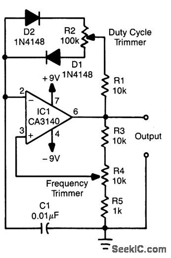
This relaxation oscillator circuit uses diodes to produce charge and discharge paths for C1. The duty cycle is set via R2 and the frequency via R4. C1 can be varied to vary the frequency ranae, which, for this circuit is approximately 300 to 3000 Hz. (View)
View full Circuit Diagram | Comments | Reading(0)
TUNNEL_DIODE_COINCIDENCE_CIRCUIT
Published:2009/7/19 21:35:00 Author:Jessie

Determines coincidence of pulses from scintillation counter within nanosecond limits, for high-energy physics experiments. Circuit has limited timing jitter, good temperature stability, and is insensitive to transistor parameters.-C. Infante and F. Pandarese, Tunnel Diodes Stabilize Coincidence Circuits, Electronics, 34:46, p 133-135. (View)
View full Circuit Diagram | Comments | Reading(1027)
| Pages:823/2234 At 20821822823824825826827828829830831832833834835836837838839840Under 20 |
Circuit Categories
power supply circuit
Amplifier Circuit
Basic Circuit
LED and Light Circuit
Sensor Circuit
Signal Processing
Electrical Equipment Circuit
Control Circuit
Remote Control Circuit
A/D-D/A Converter Circuit
Audio Circuit
Measuring and Test Circuit
Communication Circuit
Computer-Related Circuit
555 Circuit
Automotive Circuit
Repairing Circuit