
Circuit Diagram
Index 837
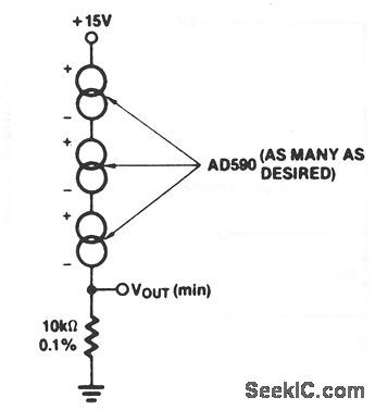
Average_temperature_sensor
Published:2009/7/19 22:06:00 Author:Jessie

This circuit shows an AD590 connected as an average-temperature sensor. The sum of the AD590 currents appears across R, which is chosen by R = (10 kΩ)/n, where n = the number of sensors. Harris Semiconductors, Data Acquisition 1991 p 12-7 (View)
View full Circuit Diagram | Comments | Reading(975)
LOW_COST_BAROMETER
Published:2009/7/10 2:28:00 Author:May

Using Linear Technology LT1027 reference and LT1078 op amps, transducer T1 is fed with 1.5mA.The pressure transducer feeds an amplifier with a gain of 10, then it feeds a voltage follower. Output can either drive an analog meter or a DVM circuit. (View)
View full Circuit Diagram | Comments | Reading(1166)
Lowest_temperature_sensor
Published:2009/7/19 22:06:00 Author:Jessie
This circuit shows an AD590 connected as a lowest-temperature sensor. The available current is that of the coldest sensor.Harris Semiconductors, Data Acquisition 1991 p 12-7 (View)
View full Circuit Diagram | Comments | Reading(802)
MUSICAL_DOORBELL
Published:2009/7/10 2:27:00 Author:May

8 to 15 Vac is applied to terminals C and D,which produces a dc voltage across R2, and turns on Q1.This connects the batteries B1 and B2 to the rest of the circuit,which activates it.Latch U3 is triggered,it remalns on until Q2 turns on,charges C2,and turns off U2.When U3 is turned on,Q3 is forward-biased,which energlzes K1,powers up U4.At the time the K1 contacts close,C4 couples a positive spike to pin 4 of U4,a melody synthesizer chip.U4 generates a pre-programmed tune,at the end of which pin 1 of U4 goes positive,This activates optocoupler U1 and turns off Q2,which drops out the relay.U2 acts as an audio amplifier, which drives an 8-Ω speaker. (View)
View full Circuit Diagram | Comments | Reading(1180)
BOOSTING_OUTPUT_CURRENT
Published:2009/7/19 22:06:00 Author:Jessie

External NPN pass transistor is added to each section of LM125 precision dual tracking regulator to in-crease maximum output current by factor equal to beta of transistor. To prevent overheating and destruction of pass transistors and result, ant damage to regulator, series resistor RCL, is used to sense load current. When voltage drop across RCL equals current-limit sense voltage in range of about 0.3 to 0.8 V (related to junction temperature), regulator will current-limit. Maximum load current is about 1A for 25℃ junction and 0.6 ohm for RCL. LM125 provides ±15V, LM126 provides ±12V, and LM127 provides +5V and -12V.-T. Smathers and N. Sevastopoulos, LM125/LM126/LM127 Precision Dual Tracking Regulators, National Semiconductor, Santa Clara, CA, 1974, AN-82, p 5. (View)
View full Circuit Diagram | Comments | Reading(593)
PULSE_COMMAND_MONITOR
Published:2009/7/19 22:06:00 Author:Jessie
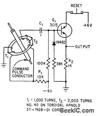
Toroid in control electrode circuit of solid-state thyratron Q1 triggers circuit on when command pulse passes through insulated conductor, without affecting command circuit for such critical functions as arming of missile.-R. C. Wright, Collecting Data from Live Missiles in Flight, Electronics, 34:12, p 46-49. (View)
View full Circuit Diagram | Comments | Reading(1232)
OSCILLATOR_D_E_T_E_C_T_O_R
Published:2009/7/19 22:06:00 Author:Jessie

Capacitor microphones form part of grid tank circuit of 6-Mc tuned-plate tuned-grid r-f oscillator that also detects 6.5-cps modulation by class-C operation during oscillation. Used in infrared analyzer for detecting leaks in automobile airsuspension systems.-P. G. Balko, Infrared Finds Auto Suspension Leaks, Electronics, 31:49, p 82-85. (View)
View full Circuit Diagram | Comments | Reading(614)
Sample_and_hold_interface_with_an_AD571_10_bit_A_D_converter
Published:2009/7/19 22:06:00 Author:Jessie

Sample-and-hold interface with an AD571 10-bit A/D converter (courtesy Analog Devices, Inc.). (View)
View full Circuit Diagram | Comments | Reading(622)
ENERGY_LOSS_TELESCOPE
Published:2009/7/19 22:05:00 Author:Jessie
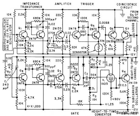
Uses sensistors to help compensate for temperature effects. Circult normally employs two identical channels for the two multiplier phototubes, to drive coincidence circuit that feeds height-to-time converter.-D. Enemark, Balloon-Borne Circuits Sort High. Altitude Cosmic Rays, Electronics, 32:35, p 52-55. (View)
View full Circuit Diagram | Comments | Reading(830)
±15V_TRACKING_1
Published:2009/7/19 22:04:00 Author:Jessie

Arrangement uses LM104 negative regulator to track positive regulator, with both regulators adjusted simultaneously by changing R1. Inverting opamp can be added to provide negative output voltage while using positive voltage as reference.-R. C. Dobkin, One Adjustment Controls Many Regulators, EDN Magazine, Nov. 1, 1970, p 33-35. (View)
View full Circuit Diagram | Comments | Reading(743)
60_MC_COMMON_BASE
Published:2009/7/19 22:04:00 Author:Jessie

Delivers 10 mw to 50-ohm load at 25℃. Collector efficiency is 10%.-Texas Instruments Inc., Transistor Circuit Design, McGraw-Hill, N.Y., 1963, p 320. (View)
View full Circuit Diagram | Comments | Reading(651)
FOOTBALL_HELMET_TRANSMITTER
Published:2009/7/19 22:04:00 Author:Jessie
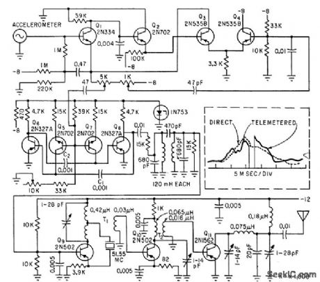
Impact data sensed by accelerometer in helmet is, transmitted to sideline receiver by f-m/f trans-miller. Use of subcarrier oscillator makes transmitter more immune to shock and vibration than with conventional main-channel oscillator.-J. S. Aagaard and J. L. DuBois, Telemetering impact Data from the Football Field, Electronics, 35:14, p 46-47. (View)
View full Circuit Diagram | Comments | Reading(1284)
5_CPS_TO_300_KC
Published:2009/7/19 22:03:00 Author:Jessie

Overcomes low-frequency problems of wide-range oscillators by using tank both for controlling frequency and coupling signal to next stage. Frequency is stable over wide variations in d-c voltage and temperature, yet circuit is inexpensive. Alternative output coupling shown is useful for driving varying loads.-J. Freeman, Low-Frequency C-Coupled Oscillator, EEE, 11:7, p 27-28. (View)
View full Circuit Diagram | Comments | Reading(589)
Absolute_temperature_sensor
Published:2009/7/19 22:03:00 Author:Jessie
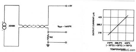
This circuit shows an AD590 that is connected as a basic absolute-temperature sensor. The output is proportional to absolute temperature, as shown by the graph. Harris Semiconductors Data Acquisition 1991, p 12-7 (View)
View full Circuit Diagram | Comments | Reading(916)
ARITHMETIC_BINARY
Published:2009/7/19 22:03:00 Author:Jessie

Uses 2N501 series-triggered transistors, catching diodes, and peaking coils operating at date input rate of about 15 Mc, in neutron time-of-flight and pulsed-neutron measurements.-E. J. Wade, Digital Instrumentation for Nuclear Research Tests, Electronics, 33:43, p 68-71.
(View)
View full Circuit Diagram | Comments | Reading(523)
Attendance_counter
Published:2009/7/19 22:02:00 Author:Jessie

This circuit shows an ICM7249 connected as an attendance counter, with the LCD display showing each increment. The battery can be replaced without disturbing operation if a 100-μF capacitor is placed in parallel with the battery before removal. Disconnect the display (if possible) during the battery replacement. After replacement, the capacitor can be removed and the display can be reconnected. Harris Semiconductors Data Acquisition 1991 p, 11-90 (View)
View full Circuit Diagram | Comments | Reading(1466)
FOUR_CHANNEL_DISCRIMINATOR
Published:2009/7/19 22:02:00 Author:Jessie

Common amplifier and four individual amplifiers drive triggers for four channels of sealers. Common amplifier supplies 7 v on common bus from Q3 to four potentiometers, settings of which determine discrimination point for each channel.-D. Enemark, Balloon-Borne Circuits Sort High-Altitude Cosmic Rays, Electronics, 32:35, p 52-55. (View)
View full Circuit Diagram | Comments | Reading(767)
VOLTAGE_CONTROLLED_BUTLER_OSCILLATOR_
Published:2009/7/19 22:02:00 Author:Jessie

Provides 70% frequency deviation. When tuned to 2 Mc, frequency deviation is -205 kc at 0 V control input and +1,289 kc at 20 V, though frequency deviation is not linearly proportional in lower half of voltage range. -C. F. Turner, Wide-Range, Voltage-Controlled Oscillator, EEE, 10:10, p 31. (View)
View full Circuit Diagram | Comments | Reading(1313)
MULTIPLEX_DRIVER
Published:2009/7/19 22:01:00 Author:Jessie

Diode matrix drives bilateral transistors similar to core memory drivers. Drive circuit is regulated to within 10%. -J. V. Dirocco and J. W. Peghiny, Low.Level Encoding Approach; Latest Details of Titan II Telemetry, Electronics, 35:47, p 36-39.
(View)
View full Circuit Diagram | Comments | Reading(476)
8085_CPU_to_cassette_tape_recorder_interface_using_one_LM324_quad_op_amp
Published:2009/7/19 22:01:00 Author:Jessie


8085 CPU to cassette tape recorder interface using one LM324 quad op amp (courtesy Intel Corporation). (View)
View full Circuit Diagram | Comments | Reading(1247)
| Pages:837/2234 At 20821822823824825826827828829830831832833834835836837838839840Under 20 |
Circuit Categories
power supply circuit
Amplifier Circuit
Basic Circuit
LED and Light Circuit
Sensor Circuit
Signal Processing
Electrical Equipment Circuit
Control Circuit
Remote Control Circuit
A/D-D/A Converter Circuit
Audio Circuit
Measuring and Test Circuit
Communication Circuit
Computer-Related Circuit
555 Circuit
Automotive Circuit
Repairing Circuit