
Circuit Diagram
Index 838
Motor_hour_meter
Published:2009/7/19 22:01:00 Author:Jessie

This circuit shows an ICM7249 that is connected as an hours-in-use meter and is capable of displaying how many hours that line voltage is applied to the motor. This configuration will operate continuously for 21/2 years using a 3-V lithium cell. Without the display (which only needs to be connected when a reading is required), the circuit will operate for about 10 years. Harris Semiconductors Data Acquisition, 1991. p 11-89 (View)
View full Circuit Diagram | Comments | Reading(1517)
Precision_frequency_counter
Published:2009/7/19 22:00:00 Author:Jessie

This circuit shows a simple 4-digit frequency counter using an ICM7217 and an ICM7207 (which provides the 1-s gating window and the STORE and RESET signals). The display reads hertz directly, as connected. With pin 11 of the ICM7027 connected to VDD, the gating time is 0. 1 s. This displays tens of hertz at the least significant digit. For shorter gating times, use a 6.5536-MHz crystal (0.01s with pin 11 connected to VD and 0.1 s with pin 11 open)
(View)
View full Circuit Diagram | Comments | Reading(2654)
G_M_COUNTER_FOR_TRACERS
Published:2009/7/19 22:00:00 Author:Jessie

Monitors radioactivity level of lowing liquids or gases for long periods of time. Concentration of 0.1 microcurie per liter of liquid gives counting rate of 200 cpm above 300-cpm background count when using iodine-131. Output pulse is 0.75 v in amplitude and 20 microsec wide.-F. E. Armstrong and E. A. Pavelka, Monitoring Radioisotope Tracers in Industry, Electronics, 32:26, p 42-43. (View)
View full Circuit Diagram | Comments | Reading(621)
RESISTANCE_CONTROLLED_OSCILLATOR
Published:2009/7/19 22:00:00 Author:Jessie

Both positive and negative feedback loops ore used, with notch network as frequency-determining element. Incandescent lamp in forward loop give amplitude stabilization. Tuning network contains resistance-to-frequency tranducers.-V. C. Vanderbilt and C. L. Zimmer, Magnetic Tape Recorder Programs Engine Dynamometer Tests, Electronics, 33:51, p 74-77. (View)
View full Circuit Diagram | Comments | Reading(838)
WIND_VELOCITY_TRANSMITTER
Published:2009/7/19 21:59:00 Author:Jessie

Batter-operated transmitter at remote mountctin site uses transmitters exclusively, for power econ to telemeter wind direction and velocity for predicting avalanches. Modulator uses nine separate 2N366 audio oscillators (not shown) that feed 2N369 class-A buffer.-R. Beaulieu and G. Neal, Wind Velocity Telemetering System, Electronics, 33:29, p 68-70.
(View)
View full Circuit Diagram | Comments | Reading(529)
4_to_20_mA_interface_using_the_454_V_F_converter_chip_with_a_10_kHz_full_scale_output
Published:2009/7/19 21:59:00 Author:Jessie

4-to-20 mA interface using the 454 V/F converter chip with a 10 kHz full scale output (courtesy Analog Devices, Inc.). (View)
View full Circuit Diagram | Comments | Reading(609)
ELECTROMETER
Published:2009/7/19 21:58:00 Author:Jessie

Amplifies output of photo-multiplier that responds to degree of fluorescence, which in turn is proportional to radiation received by glass dosimetry needle implanted in body of person undergoing radiation treatment.-S. J. Malsky et al, Measuring Radiation Within Human Body, Electronics, 33:12, p 74-75. (View)
View full Circuit Diagram | Comments | Reading(0)
8085_CPU_to_multiple_peripherals_interface
Published:2009/7/19 21:57:00 Author:Jessie

8085 CPU to multiple peripherals interface (courtesy Intel Corporation). (View)
View full Circuit Diagram | Comments | Reading(1093)
LOGARITHMIC_AMPLIFIER_FOR_05_TO_6_V_D_C
Published:2009/7/19 21:57:00 Author:Jessie

Uses operational amplifer and function generator principle lo compress detector signal levels to values within range of telemetering system.-S. Chase, Jr. and F. Schwarz, Mariner II Instrumentation: What Will It See on Venus ?, Electronics, 35:50, p 42-45. (View)
View full Circuit Diagram | Comments | Reading(1022)
30_MC_WIDE_TEMPERATURE_RANGE
Published:2009/7/19 21:57:00 Author:Jessie

Operates over range of -40 to +60℃. Typical power output is 23 mw at lowest temperature and 20 mw at highest. Collector efficiency is 30%.-Texas Instruments Inc., Solid-State Communications, McGraw-Hill, N.Y., 1966, p 239. (View)
View full Circuit Diagram | Comments | Reading(614)
Simple_unit_counter_with_BCD_output
Published:2009/7/19 21:56:00 Author:Jessie

This circuit shows an ICM7217 and a calculator-type 4-digit display that is connected to form a very simple unit counter and display system. (View)
View full Circuit Diagram | Comments | Reading(1458)
F_M_F_M_TRANSMITTER
Published:2009/7/19 21:56:00 Author:Jessie
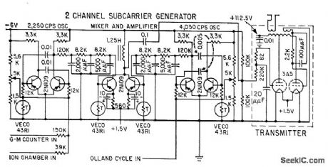
Output power is 0.5 w at 95 Mc, and range is 400 miles. Provides two channels.-L. E. Peterson, R. L. Howard, and J. R. Winckler, Balloon Gas Monitors Cosmic Radiation, Electronics, 31:45, p 76-79. (View)
View full Circuit Diagram | Comments | Reading(988)
27255_MC_TUNNEL_DIODE_CRYSTAL_OSCILLATOR
Published:2009/7/19 21:56:00 Author:Jessie

Operates within tolerance of quartz crystal from -55 to + 85℃ and bias range of 110 to 150 mv for Citizens Band service. - Transistor Manual, Seventh Edition, General Electric Co., 1964, p 353. (View)
View full Circuit Diagram | Comments | Reading(572)
Inexpensive_frequency_counter_tachometer
Published:2009/7/19 21:56:00 Author:Jessie

This circuit shows an ICM7217 and an ICM7555 that are connected as a basic frequency counter. The connections between the ICM7217 and a common-cathode LED display are shown in Fig. 12-18. The frequency counter is calibrated (against a known standard) using RA as a coarse control and RB as a fine control.Notice that the ICM7555 timer is connected as an astable multivibrator. Harris Semiconductors, Data Acquisition 1991 p 11 55 (View)
View full Circuit Diagram | Comments | Reading(4134)
GAMMA_RAY_DETECTOR
Published:2009/7/19 21:55:00 Author:Jessie

Triggers only on gammaray pulse produced by nuclear explosion. Uses a-c coupled ion chamber to detect pulses of gamma radiation.-J. C. Champeny, T. E. Petriken, and S. Siciliano, Nuclear Bomb Alarm Systems, Electronics, 32:19, p 53-55. (View)
View full Circuit Diagram | Comments | Reading(2195)
±15V_TRACKING_AT_100mA
Published:2009/7/19 21:55:00 Author:Jessie

Provides line and load regulation of 0.075% by using CA3094A programmable opamp and CA3085A series voltage regulator. V+ input range is 19 to 30V for 15-V output, while V- input range is -16 to -30 V for -15 V output.- Circuit Ideas for RCA Linear ICs, RCA Solid State Division, Somerville, NJ, 1977, p 18. (View)
View full Circuit Diagram | Comments | Reading(654)
VOLTAGE_CONTROLLED_VFO
Published:2009/7/19 21:55:00 Author:Jessie

Adding 10K resistor to basic ujt oscillator gives voltage-controlled variable-frequency oscillator. With 0.68 mfd for C, d-c input voltage range of 0 to 30 V gives 670 to 4,550 pps. With 0.2 mfd for C, same input range gives 220 to 1,400 pps. Not intended for use where linearity is important.-B. Strunk, Voltage-Controlled Variable-Frequency Oscillator, EEE, 10:12, p 28-30. (View)
View full Circuit Diagram | Comments | Reading(665)
TWO_CHANNEL_DIVERSITY_COMBINER
Published:2009/7/19 21:55:00 Author:Jessie
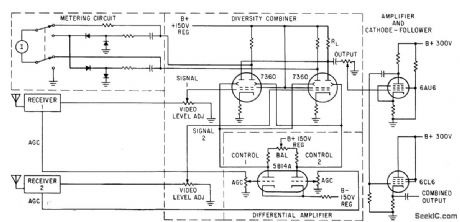
Beam-deflection lubes provide ratio-squared combining of two telemetry receiving channels, to counteract fading signals from tumbling or spinning spacecraft missile. Video signals go directly to control grids of type 7360 defiection tubes, while control voltages from receivers are applied to the respective deflection electrodes through differential amplifier,-V,A.Rafner, Telemetry Diversity Combiner Uses Beam Deflection Technique, Electronics, 35:4, p 42-43.
(View)
View full Circuit Diagram | Comments | Reading(1119)
MULTIPLE_FEEDBACK_R_C_OSCILLATOR
Published:2009/7/19 21:54:00 Author:Jessie

Gives excellent amplitude stability and low distortion. Uses vibration and shockproof version of Sulzer bridged-T configuration to provide single-frequency operation in 4-cps to 350-kc range.-L. H. Dulberger, Improved R-C Oscillator, Electronics, 32:10, p 62. (View)
View full Circuit Diagram | Comments | Reading(610)
0_15V
Published:2009/7/19 21:54:00 Author:Jessie

Addition of 307 or 301A opamp and three inexpensive components to standard three-terminal voltage regulator provides programming capability from maximum terminal voltage down to zero. With adequate heatsink, output current can be up to 1A. Opamp A2 provides floating reference voltage to normally grounded common terminal of A1, with pot allowing ground to be positioned anywhere along voltage drop of 15V across pot. Unregulated negative supply is not critical, and drain is 10 mA.-W. G. Jung, Three Components Program Regulator from Maximum to Zero, EDN Magazine, May 20, 1977, p 126 and 128. (View)
View full Circuit Diagram | Comments | Reading(1019)
| Pages:838/2234 At 20821822823824825826827828829830831832833834835836837838839840Under 20 |
Circuit Categories
power supply circuit
Amplifier Circuit
Basic Circuit
LED and Light Circuit
Sensor Circuit
Signal Processing
Electrical Equipment Circuit
Control Circuit
Remote Control Circuit
A/D-D/A Converter Circuit
Audio Circuit
Measuring and Test Circuit
Communication Circuit
Computer-Related Circuit
555 Circuit
Automotive Circuit
Repairing Circuit