
Circuit Diagram
Index 839
GATED_AMPLIFIER_FOR_RECEIVER
Published:2009/7/19 21:54:00 Author:Jessie
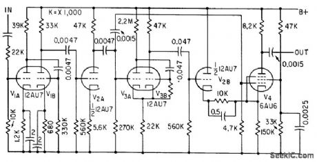
Input from f-m discriminator of ground receiver for neutron-detecting radiosonde contains two sub-carrier oscillator frequencies plus sleep un wanted pulses at audio blocking rate of 10 to 200 cps. Three-stage amplifier feeds amplified input signals to one-shot mvbr V3A-V3B for blocking of unwanted pulses. Out-put of gated amplifer V4 then contains only bursts of the two desired subcarrier frequencies.-L. Hillman and It. C. Haymes, Modifying a Telemetry System for Balloon-Borne Neutron Detection, Electronics, 34:11, p 60-63. (View)
View full Circuit Diagram | Comments | Reading(661)
Basic_digital_thermometer
Published:2009/7/19 21:53:00 Author:Jessie

This circuit shows an ICL7182 bargraph converter that is connected to form a basic digital thermometer, with a bargraph readout. The connections between the ICL7182 and bargraph are shown in Fig. 12-14. Harris Semiconductors Data Acquisition.1991 p 2-145 (View)
View full Circuit Diagram | Comments | Reading(1439)
8080A_CPU_module_to_8255A_interface
Published:2009/7/19 22:32:00 Author:Jessie


8080A CPU module to 8255A interface. This circuit comes complete as the Intel SDK 80 kit board. All of the 8255A interface lines are directly driven by the CPU (courtesy Intel Corporation). (View)
View full Circuit Diagram | Comments | Reading(1630)
RESONANT_REED_PAGING_RECEIVER
Published:2009/7/19 22:31:00 Author:Jessie

Fertile antenna L1 is tuned to one of up to 45 different carrier frequencies in range from 15 to 30 kc, keyed at various repetition rates. Resonant relay K1 in collector circuit of detector Q5 vibrates when excited at its natural keying rate, thereby interrupting loudspeaker current at audio rate to create paging tone.-J. G. DeGraaf, Selective Paging System Uses Coded Transmission, Electronics, 33:9, p 68-70. (View)
View full Circuit Diagram | Comments | Reading(670)
SYNCHRONIZED_OSCILLATOR
Published:2009/7/19 22:30:00 Author:Jessie

Astable mvbr Q1-Q2 operating at68.4 kc is synchronized by 400-cps signal having 6-microsec pulse width. Frequency stability can be one part in 4,000 if film resistors and other temperature-stable components are used. Synchronizing signal is variable, of the order of 1/170 of oscillator frequency but with no integral relationship between the signals.-G. Silver-man. A Synchronized Oscillator Circuit, EEE, 10:7, p 29-30. (View)
View full Circuit Diagram | Comments | Reading(0)
RESISTANCE_CONTROLLED_SUBCARRIER_OSCILLATOR
Published:2009/7/19 22:30:00 Author:Jessie
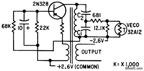
Required 7.5% frequency deviation is obtained with ratio of 1.5 for C1/C2.-H. L. Richter et al., Instrumenting the Explorer I Sotellite, Electronics, 32:6, p 39-43. (View)
View full Circuit Diagram | Comments | Reading(1016)
Simple_precision_barometer
Published:2009/7/19 22:30:00 Author:Jessie

This circuit uses a semiconductor-based pressure transducer to form a low-cost simple barometer, and produces a 0- to 3.054-V output, in response to a sensed 0 to 30.54-in Hg. Transducer T1 specifies a nominal 115 mV at full scale, although each device is supplied with precise calibration data. To calibrate, adjust the potentiometer at A2 until the output corresponds to the scale factor that is supplied with the transducer. Linear Technology Corporation 1991 AN45-11
(View)
View full Circuit Diagram | Comments | Reading(919)
CURRENT_BOSTING_WITH_ELECTRONIC_SHUTDOWN
Published:2009/7/19 22:30:00 Author:Jessie

Circuit provides complete shutdown for both sections of National LM125 dual tracking regulator without affecting unregu-Iated inputs that may be powering additional equipment. Shutdown control signal is TTL-compatible, but regulator may be shut down at any desired level by adjusting values of R8 and R9. Control signal is used to short internal reference voltage of regulator to ground, thereby forcing positive and negative outputs to about +700 mV and +300 mV respectively. When shutdown signal is applied, Q4 draws current through R3 and D2, establishing voltage VR that starts current sourcesQ1 and Q2. Currents I1, I2, and I3 are then equal so both sides of regulator are shut down simultaneously.-T. Smathers and N. Sevastopoulos, LM125/LM126/LM127 Precision Dual Tracking Regulators, National Semiconductor, Santa Clara, CA, 1974, AN-82, p14. (View)
View full Circuit Diagram | Comments | Reading(706)
Battery_powered_relative_humidity_signal_conditioner
Published:2009/7/19 22:29:00 Author:Jessie

This circuit produces a 0- to 1.00-V output in response to a sensed 0 to 100% relative humidity (RH), and operates from a 9-V battery. To calibrate, place the sensor in a 5% RH environment, and set the 5% RH trim for 50 mV at the output. Then, place the sensor in 90% RH and set the 90% trim for 900-mV output.Repeat as necessary. If the known RH environments are not available, the capacitance-versus-RH table in Fig. 12-35 can be used (although the table applies to an ideal sensor). The capacitor values can be built-up or directly dialed on a precision variable air capacitor (General Radio #722D). Linear Technology Corporation 1991 AN45-10 (View)
View full Circuit Diagram | Comments | Reading(673)
CURRENT_CONTROLLED_SUBCARRIER_OSCILLATOR
Published:2009/7/19 22:29:00 Author:Jessie

Uses time-controlled reactance modulation. Operating frequency is altered by in. troducing alternating current having same frequency but 90° out of phase with oscillator voltage. Frequency shift thus produced is proportional to amount of additional current fed into tuned circuit.-H. L. Richler et al., Instrumenting the Explorer I Satellite, Electronics, 32:6, p 39-43. (View)
View full Circuit Diagram | Comments | Reading(1209)
PROJECTILE_NOSE_PRESSURE_TELEMETER
Published:2009/7/19 22:28:00 Author:Jessie
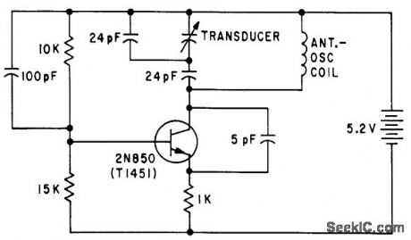
Variable-capacitance pressure transducer modulates 150-Mc carrier for telemetering stagnation pressure at nose of projectile during flight. Antenna-oscillator coil has four turns of No. 24 AWG wire, 0.16 inch inside diameter.-O. H. Bock and P. L. Clemens, Aerodynamic Measurements in a Hypervelocity Gun Range, Electronics, 34:44, p 33-37. (View)
View full Circuit Diagram | Comments | Reading(1300)
FIVE_FREQUENCY__OSCI_LLATOR
Published:2009/7/19 22:28:00 Author:Jessie
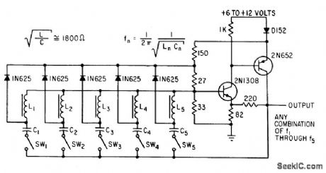
Two-transistor circuit generates up to five different tones simultaneously for five-bit parallel encoder for telemetry. Starting transients ore built up in individual series-tank circuits. Amplitude of oscillation stabilizes al value where energy from negative-resistance source equals energy lost in tanks.-R. Stapelfeldt, Multitone Oscillators-New Source of Simultaneous Frequencies, Electronics, 36:1, p 86-87. (View)
View full Circuit Diagram | Comments | Reading(4081)
RADIATION_ALARM_FAILURE_DETECTOR
Published:2009/7/19 22:28:00 Author:Jessie

Neon indicator lamp comes on when counter flip-flop of radioactive dust particle alarm stops. Flip-flop normally operates at minimum of 10 transitions per second due to slight leakage from radioactive test source built into detector.-H. E. DeBolt, How Radiation Monitor Guards Nuclear Navy, Electronics, 33:4, p 43-45. (View)
View full Circuit Diagram | Comments | Reading(746)
Temperature__to_frequency_converter
Published:2009/7/19 22:27:00 Author:Jessie

This circuit produces a 0- to 1-kHz output in response to a sensed 0 to 1 00℃ temperature range. Cold-junction compensation is included, and accuracy is within 1℃ with stable 0. 1℃ resolution. A single 4.75- to 10-V supply is required, with a maximum current consumption of 360μA. To calibrate this circuit, disconnect the thermocouple and drive point A with 4.06 mV. Then, set the 1.5-kΩ trim for exactly 1000-Hz output. Connect the thermocouple and the circuit is ready for use. Recalibration is not required if the thermocouple is replaced. Linear Technology Corporation 1991 AN45-8 (View)
View full Circuit Diagram | Comments | Reading(645)
DUAL_TRACKING
Published:2009/7/19 22:35:00 Author:Jessie


Uses one 759 power opamp for positive output, connected to track with 79MG negative voltage regulator having adjustable output. Common-mode range of 79MG includes ground, permitting operation from single supply. Circuit can also be built with two power opamps, one inverting and the other noninverting.-R. J. Apfel, Power Op Amps-Their Innovative Circuits and Packaging Provide Designers with More Options, EDN Magazine,Sept. 5, 1977, p 141-144. (View)
View full Circuit Diagram | Comments | Reading(1234)
8085A_CPU_to_8202_interface_with_no_read_or_write_wait_states
Published:2009/7/19 22:34:00 Author:Jessie

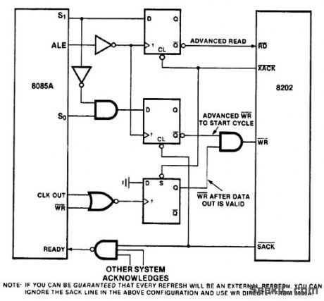
8085A CPU to 8202 interface with no read or write wait states (courtesy Intel Corporation). (View)
View full Circuit Diagram | Comments | Reading(873)
15_V_powered_radiation_detector
Published:2009/7/19 22:34:00 Author:Jessie

This circuit provides an audible tick signal each time radiation or a cosmic ray passes through the detector. The LT1073 switching regulator pulses T1 which, in turn, drives a voltage tripler to provide 500-V bias to the detector. R1 and R2 provide feedback to the LT1073, which closes the control loop. No calibration is needed. Linear Technology Corporation, 1991, AN45-11. (View)
View full Circuit Diagram | Comments | Reading(747)
MEASURING_SIGNALS_IN_NOISE
Published:2009/7/19 22:34:00 Author:Jessie

Lock-in amplifier beats desired weak signal (40 db below input noise level) with reference signal of same frequency, to give d-c cutout that can be measured or recorded, as required in radio astronomy. Bandwidth is variable down to 0.12 cps for tuning range of from 15 to 15,000 cps. Also used for checking oscillafor frequency against WWV to one part in 1010.-R. D. Moore, Lock-In Amplifier for Signals Buried in Noise, Electronics, 35:23, p 40-43. (View)
View full Circuit Diagram | Comments | Reading(2625)
PULSE_RESHAPER
Published:2009/7/19 22:33:00 Author:Jessie
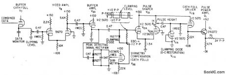
Serves as output amplifier for pcm and pdm signals from diversity combiner circuit. Over-amplification and dipping stages give fast rise and decay time without risk of false triggering.-W. Casson and R. C. Robinson, Versatile Diversity Combiner Handles Most Missile-Range Signals, Electronics, 35:44, p 40-43.
(View)
View full Circuit Diagram | Comments | Reading(830)
±15V_TRACKING_AT_1A
Published:2009/7/19 22:33:00 Author:Jessie

Positive regulator tracks negative. IfQ1 and Q2 are perfectly matched, tracking action is unchanged over full operating temperature range, with tracking betterthan 100 mV. Regulationfrom no load to full load is 10 mV for positive side and 45 mV for negative side.- Linear Applications, Vol. 2, National Semiconductor, Santa Clara, CA, 1976, AN-103, p 8-9. (View)
View full Circuit Diagram | Comments | Reading(890)
| Pages:839/2234 At 20821822823824825826827828829830831832833834835836837838839840Under 20 |
Circuit Categories
power supply circuit
Amplifier Circuit
Basic Circuit
LED and Light Circuit
Sensor Circuit
Signal Processing
Electrical Equipment Circuit
Control Circuit
Remote Control Circuit
A/D-D/A Converter Circuit
Audio Circuit
Measuring and Test Circuit
Communication Circuit
Computer-Related Circuit
555 Circuit
Automotive Circuit
Repairing Circuit