
Circuit Diagram
Index 849
FET_SOURCE_FOLLOWER
Published:2009/7/10 1:53:00 Author:May
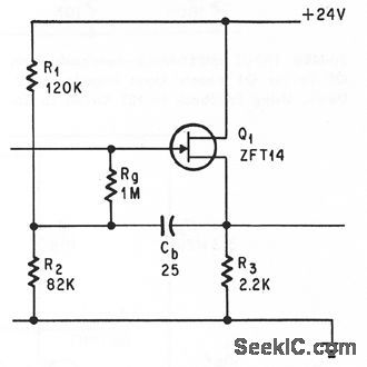
Voltage-divider biasing increases input impedance. R3 provides negative feedback.-B. Down, Using Feedback in FET Circuit to Reduce Input Capacitance, Electronics, 37:31, p 63-65.
(View)
View full Circuit Diagram | Comments | Reading(1194)
555_BEEP_TRANSFORMER
Published:2009/7/10 1:53:00 Author:May

The simple circuit transforms the steady beep of an audible-signal device, such as a Mallory sonalert, into a distinctive warble or chirp. The value of C2 determines just what tone color you'll get. With the 1-μF value shown, the circuit produces a warble similar to the ring tone of an inexpensive phone. A 10-μF value produces a chirp similar to a truck's back-up alarm. One elaboration of this circuit would be to use the second section of a 555 timer to drive a piezoelectric transducer instead of a sonalert; that modification would vary the tone's pitch, as well as the chirp rate. (View)
View full Circuit Diagram | Comments | Reading(1433)
LIGHT_RECEIVER
Published:2009/7/10 1:52:00 Author:May

T3 is a photocell or phototransistor. T4 controls the emitter voltage of T3. IC1 is an audio amplfier to provide amplification of the signal from the photocell. (View)
View full Circuit Diagram | Comments | Reading(951)
4_watt_AF_amplifier_using_an_ECG735_class_A_driver_and_an_ECG153_audio_output
Published:2009/7/20 1:43:00 Author:Jessie

4-watt AF amplifier using an ECG735 class A driver and an ECG153 audio output. This is a typical automotive tape player amplifier (courtesy GTE Sylvania Incorporated).
(View)
View full Circuit Diagram | Comments | Reading(567)
LOW_NOISE_FET_AMPLIFIER
Published:2009/7/10 1:52:00 Author:May
Agc feedbackextends imput level to 150 mv.-L.E.Clark,E.B.Mack,and R.C.Heihall,Highlights of Small-Signal Circuit Design,Electronics,36;49,p 46-50. (View)
View full Circuit Diagram | Comments | Reading(756)
RADIO_CONTROL_FOR_MOTOR
Published:2009/7/20 1:42:00 Author:Jessie

Proportional control system produces control pulses every 20 ms, with length of each adjustable between 1 and 2 ms. Circuit removes first 1 ms of pulse and expands remainder to produce 0-20 ms pulses for driving motor. Pulsing of motor gives smoother control than resistors, particularly at very low speeds. Transistor types are not critical. Tr5 can be OC28. Optional dashed connection of 8.2K resistor provides foldback current/voltage protection.-M. Weston, Variable-Speed Radio Control Motor, Wireless World, Feb. 1978, p 59. (View)
View full Circuit Diagram | Comments | Reading(771)
ELECTRONIC_SIREN
Published:2009/7/10 1:52:00 Author:May

The wailing sound of a siren is generated by a VFO consisting of Q1 and Q2. Capacitor C2 provides the feedback for the oscillator. The frequency of the oscillator is varied by the voltage applied to the base of Q1 hrough R3 .When switch S1 is closed, capacitor C1 charges, thus increasing the oscillator frequency.When S1 is released, capacitor C1 discharges, and the oscillator frequency decreases. Capacitor C3 limits the maximum oscillator frequency. The average battery current drain is about 15 mA. (View)
View full Circuit Diagram | Comments | Reading(2583)
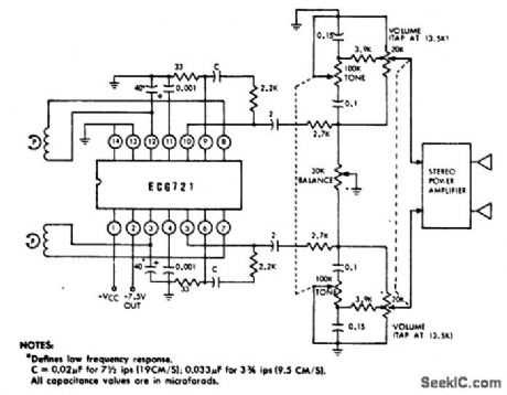
Stereo_phono_AF_preamplifier_with_RIAA_equalization
Published:2009/7/20 1:41:00 Author:Jessie

Stereo phono AF preamplifier with RIAA equalization. Gain is 40 dB at 1 kHz with the input overload point set at 80 mV RMS. Noise level is 2 μV referred to the input. Signal to noise ratio is 74 dB below 10 mV. Channel separation at 1 kHz is 80 dB (courtesy GTE Sylvania Incorporated). (View)
View full Circuit Diagram | Comments | Reading(789)
SIMPLE_CAPACITOR_TESTER
Published:2009/7/10 1:51:00 Author:May


An LM3909 LED flasher is used as an oscillator,and the capacitor connected to the terminals determines frequency.
The LED can be used to count frequency visuallyusmg a stopwatch for large capacitors(C>500μF). (View)
View full Circuit Diagram | Comments | Reading(1343)
REMOTE_SWITCHING
Published:2009/7/20 1:41:00 Author:Jessie

Uses four flip-flops, each having one 4-input and one 2-input CMOS NAND gate. Momentarily grounding any input drives corresponding output high and all other outputs low, Unless power is interrupted, additional pulses on same input have no effect; circuit remains stable until some other input is momentarily grounded. Outputs can be used to drive other logic devices directly or through buffer if current required exceeds 10 mA. Can be used for remote frequency control of VHF transceiver and for other applications requiring remote selection of mutually exclusive functions.-P. Shreve, Remote-Switching Circuit, Ham Radio, March 1978, p114. (View)
View full Circuit Diagram | Comments | Reading(702)
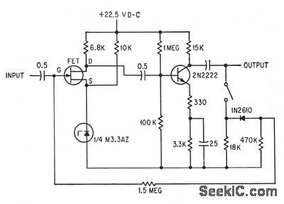
WIDEBAND_FET
Published:2009/7/10 1:51:00 Author:May

Feedback and bootstrapping techniques give overall input capacitance of 0.4 pf for 30-pf gate capacitance of fet.Transislor serves as source follower.-B. Down, Using Feedback in FET Circuit to Reduce Input Capacitance, Electronics, 37:31, p 63-65. (View)
View full Circuit Diagram | Comments | Reading(842)
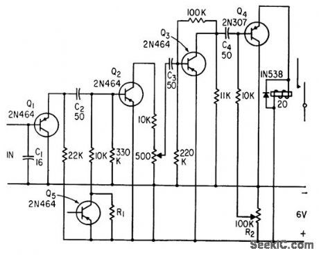
VERTICAL_ACCELERATION_RECORDER
Published:2009/7/20 1:40:00 Author:Jessie
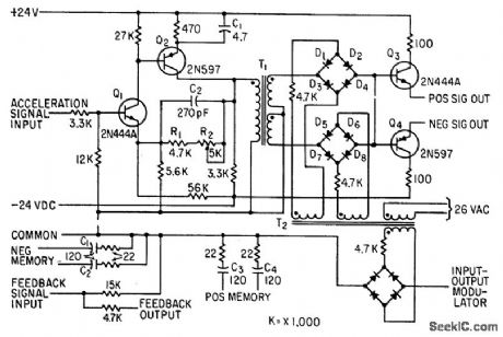
Accepts phase-reversible 40-cps signal from vertical accelerometer, which is in phase with reference voltage for positive accelerations and 180°out of phase for negative. After amplification by Q1-Q2, synchronous demodulator diodes D1 to D8 separate positive and negative signals for output transistors Q3 and Q4, which feed servo of engraved-foil flight recorder.-H. E. Schauwecker, Data Recorder for Airplane Flight Analysis, Electronics, 33:48, p 118-120. (View)
View full Circuit Diagram | Comments | Reading(1404)
16_CHOICESWITH_3_WIRES
Published:2009/7/20 1:39:00 Author:Jessie

Developed for use with mobile transceiver mounted in trunk of car, to give full independent selection of eight transmit and eight receive frequencies with only three wires running to control head on dash. System involves converting 8-position switch selection in control head to 3-bit binary form for control wires, then decoding with relays. Miniature SPST relay in control head is operated by normal push-to-talk circuit to change channel selector switch when transmitting.-G. D. Rose, Independent 8-Channel Frequency Selection with Only Three Wires, QST, Aug.1974, p 36-40. (View)
View full Circuit Diagram | Comments | Reading(572)
μP_CONTROLLED_NEGATIVE_VOLTAGE_CONVERTER
Published:2009/7/10 1:49:00 Author:May

This circuit was used to produce a variable negative voltage for contrast control of an LCD display. A 74F374 generates a square wa:ze that is ac coupled to a rectifter and load. By using the μP clock and data from the processor bus, and properly timed load signal, the dc level generated can be controlled by the μP. (View)
View full Circuit Diagram | Comments | Reading(527)
ALTERNATE_WARBLE_TONE_SIREN
Published:2009/7/10 1:49:00 Author:May

This circuit uses two NE555 timers to generate a warble tone. IC1 frequency shifts IC2 by feeding a square waxe to pin 5, the modulation input of IC2. IC1 runs at about 1 Hz (View)
View full Circuit Diagram | Comments | Reading(826)
1_CPS_RAIL_FLAW_AMPLIFIER
Published:2009/7/20 1:39:00 Author:Jessie
Used to amplify extremely low-frequency signals produced by longitudinal defects in rails, to drive pen recorder. C1 bypasses high-frequency signals.-H. W. Keevil, Transistor Pulse Amplifiers Detect Rail Faults, Electronics, 35:21, p 53-54. (View)
View full Circuit Diagram | Comments | Reading(977)
GROUNDED_GRID_BROADBAND
Published:2009/7/10 1:48:00 Author:May

Grounded-cathode preamplifier has plate load that provides increasing gain with increasing frequency to drive following two tubes in cascade. Both source and load impedances are 50 ohms.-Broadband VHF Amplifier Covers 30 to 260 Mc Range, Electronics, 35:4, p 102. (View)
View full Circuit Diagram | Comments | Reading(761)
DUTY_CYCLE_MEASURER
Published:2009/7/10 1:48:00 Author:May
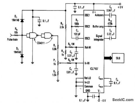
An Intersil 7101 31/2-digit A/D converter is used to display the duty cycle of a pulse train as a percent-age. The frequency range of this circuit is 100 Hz to 250 kHz. The CM0S gates convert the pulse train to constant amplitude. This amplitude is then compared to a reference of 1V, derived from R3 and R4. P1 is for calibration. (View)
View full Circuit Diagram | Comments | Reading(581)
Stereo_tape_system_AF_preamplifier_with_simple_tone_control
Published:2009/7/20 1:38:00 Author:Jessie
Stereo tape system AF preamplifier with simple tone control. Current drain at 12 volts is typically 16 mA. Voltage gain is 68 dB. Channel separation is typically 60 dB (courtesy GTE Sylvania Incorporated). (View)
View full Circuit Diagram | Comments | Reading(829)
HEE_HAW_SIREN
Published:2009/7/10 1:48:00 Author:May

A pair of timer IC's are the heart of a circuit that simulates the warbling hee-haw of a British police siren. One of the 555 timers, U2, is wired as an astable multivibrator operating at about 900 Hz. The other, U1, operates at approximately 1 Hz. Its output at pin 3 is a square wave with a 50% duty cycle-on and off cycles of about 0.5 second each. The output of U1 is applied to pin 5, the control-voltage terminal of U2. The frequency of the 555 timer IC is relatively independent of supply voltage, but can be varied ever a fairly wide range by applying a variable voltage between pin 5 and ground. When U1's output becomes high, U2 operates at about 800 kHz. That switching between two frequencies produces the warbling hee-haw signal. (View)
View full Circuit Diagram | Comments | Reading(2907)
| Pages:849/2234 At 20841842843844845846847848849850851852853854855856857858859860Under 20 |
Circuit Categories
power supply circuit
Amplifier Circuit
Basic Circuit
LED and Light Circuit
Sensor Circuit
Signal Processing
Electrical Equipment Circuit
Control Circuit
Remote Control Circuit
A/D-D/A Converter Circuit
Audio Circuit
Measuring and Test Circuit
Communication Circuit
Computer-Related Circuit
555 Circuit
Automotive Circuit
Repairing Circuit