
Circuit Diagram
Index 872
Complete_AM_FM_broadcast_receiver_with_1_watt_output_and_powered_by_6_volts
Published:2009/7/20 3:27:00 Author:Jessie
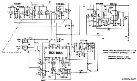
Complete AM/FM broadcast receiver with 1-watt output and powered by 6 volts.All coils and transformers are standard and can be purchased at Radio Shack.FM sensitivity is 1 μV,while AM is 30 μv(courtesy GTE Sylvania Incorporated). (View)
View full Circuit Diagram | Comments | Reading(751)
DELAYED_SWEEP_ADAPTER
Published:2009/7/20 3:26:00 Author:Jessie
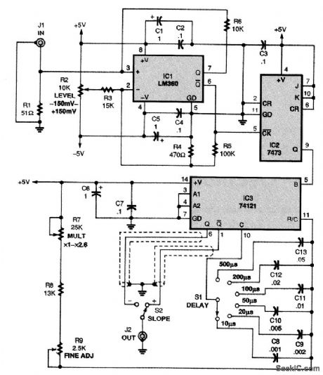
The schematic for the delayed sweep adapter is shown in the figure. Power for the circuit is pro-vided by a dual-polarity, 5-V supply. An LM360 high-speed comparator (IC1) with complementary TTL outputs is at the heart of the circuit. A trigger-level control, potentiometer R2, allows the adapter to trigger on any part of the waveform being displayed. With the values shown, the circuit functions well with a Hitachi V-212 oscilloscope, whose channel 1 output is about 25 mV per vertical division of the signal display. Assuming a normal display of about six divisions, the level control pro-vides a range of ±150 mV. You can change that range to suit your scope output by adjusting the ratio of R3 (15,000 Ω) to R4 (470 Ω); however, maintain the ratio of R5 (100,000 Ω) to R4 (470 Ω) for proper hysteresis. Resistor R1 (51 Ω) terminates the 50-Ω cable from the channel 1 output jack. IC2, a 7473 TTL dual J/K flip-flop, is configured in its toggle mode to divide the input frequency by 2. That ensures that IC3, a 74121 TTL monostable multivibrator, will function accurately over the in-put waveform's full time period. The pulse output from IC3 is coupled to the trigger-input jack of your oscilloscope, and the slope is selected via S2 to match the slope selected on your oscilloscope. Po-tentiometer R9 allows fine positioning of the trace and potentiometer R7 allows the output pulse width selected to be multiplied by a factor from x1 to over x2.5. Switch S1 lets you select the de-sired pulse width by switching in C8 through C13, in a 1-2-5 sequence. The adapter circuit was de-signed to operate on an external ±5-V, 100-mA power supply to avoid 60-Hz pickup in the unit. (View)
View full Circuit Diagram | Comments | Reading(2111)
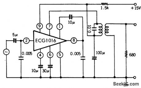
Complete_limiting_FM_IF_amplifier_and_detector
Published:2009/7/20 3:25:00 Author:Jessie
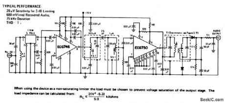
Complete limiting FM IF amplifier and detector.Typical AM rejection is 60dB,ECG746 is an 8-pin DIP and ECG750 is a 14-pin DIP.The ECG750 is designed for use with a Foster-Seeley discriminator or radio detector.Transformer T1 is a 10.7 MHz Foster-Seeley discriminator with a primary impedance of 3.9K and a peak-to-peak separation of 600 kHz. The discriminator diodes are ECG110MP(courtesy GTE Sylvania Incorporated). (View)
View full Circuit Diagram | Comments | Reading(1088)
2_watt_AF_power_amplifier_with_bass_boost_for_a_16_ohm_load
Published:2009/7/20 3:25:00 Author:Jessie
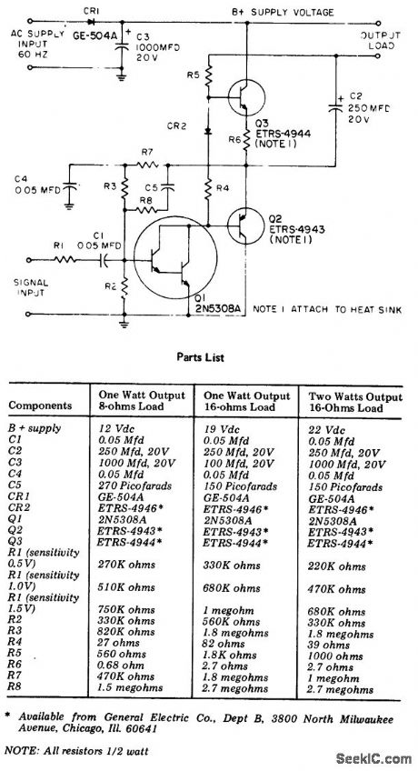
2-watt AF power amplifier with bass boost for a 16-ohm load (courtesy General Electric Company). (View)
View full Circuit Diagram | Comments | Reading(643)
OPTICALLY_ISOLATED_PRECISION_RECTIFIER
Published:2009/7/20 3:24:00 Author:Jessie


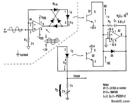
An isolation amplifier and precision rectifier can be combined in one topology, as demonstrated here. It achieves excellent rectification symmetry, zero stability, and good linearity (better than 1 per-cent) and frequency response (>>10kHz), with a minimum of precision components. A1 acts as a volt-age-to-current converter by serving the current through the D1 to D4 bridge and L1. Therefore, the voltage developed across R1 equals the instantaneous input voltage. The diode bridge's full-wave rectification causes L1 to be forward-biased, regardless of the polarity of the input voltage. The magnitude of the bias controls the intensity of optical coupling between L1 and Q1, and, thereby, the magnitude of Q1's collector current. A2 servos the current through L2 and R2 so that the current passed by Q2 balances that passed by Q1. Because of the good tracking of elements of the PS2501-2 dual optoisolator, a constant ratio exists between the L1 and L2 currents. Consequently, R2 can be adjusted so that the out-put voltage across R2 is equal to the rectifier's isolated input voltage. R3 and C1 provide frequency com, pensation for the L2-Q2 feedback loop. D5 prevents potentially destructive reverse bias of L2. (View)
View full Circuit Diagram | Comments | Reading(1294)
FM_IF_amplifier_with_quadrature_detector
Published:2009/7/20 3:23:00 Author:Jessie

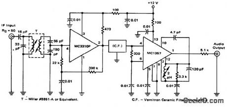
FM IF amplifier with quadrature detector (courtesy Motorola Semiconductor Products Inc.). (View)
View full Circuit Diagram | Comments | Reading(908)
AM_radio_receiver_with_a_maximum_sensitivity_of_362_dB_m_at_1000_kHz
Published:2009/7/20 3:22:00 Author:Jessie
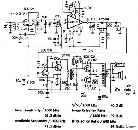
AM radio receiver with a maximum sensitivity of 36.2 dB/m at 1000 kHz.Available sensitivity is 41.5 dB/m at 1000 kHz.Sign alto noise ratio is 40.5 dB.Image rejection ratio is 39.0 dB at 1400 kHz.IF rejection ratio at 600 kHz is 39 dB.IF transformers and audio transformers are standard and can be purchased at Radio Shack,The same is true for the tuning capacitor(courtesy GTE Sylvania Incorporated). (View)
View full Circuit Diagram | Comments | Reading(719)
AF_preamplifier_with_a_thin_film_hybrid_module
Published:2009/7/20 3:22:00 Author:Jessie
AF preamplifier with a thin-film hybrid module. Output is between 0.42 and 0.90 volts at 1 kHz with a 2 mV input. Distortion is less than 3%. The AF transformer is standard and can be purchased at Radio Shack (courtesy GTE Sylvania Incorporated). (View)
View full Circuit Diagram | Comments | Reading(577)
The automobile steering alarm (4)
Published:2011/7/22 21:39:00 Author:qqtang | Keyword: steering alarm
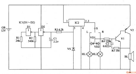
Here is to introduce an automobile steering alarm which can not only be the steering flash sound alarm, but also be the danger alarm.The working principle of the circuitThe automobile steering alarm consists of the low-frequency oscillator, electric switch circuit, control circuit, photoelectric display circuit and music alarm circuit and so on, see as figure 7-127.
The low frequency oscillator consists of the NAND circuits of D3 and D4 in the integrated circuit ICl(Dl-D4) and the external elements. (View)
View full Circuit Diagram | Comments | Reading(390)
Low_noise_preamplifier_using_an_ECG1152_13_pin_module
Published:2009/7/20 3:21:00 Author:Jessie
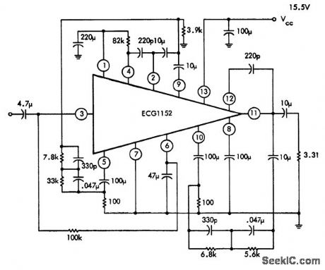
Low-noise preamplifier using an ECG1152 13-pin module. The ECG1152 is a dual two-stage direct-coupled amplifier. Typical voltage gain is 75 dB. Input resistance is 50K (courtesy GTE Sylvania Incorporated). (View)
View full Circuit Diagram | Comments | Reading(519)
ANTENNA_PHASING_CONTROL
Published:2009/7/20 3:21:00 Author:Jessie
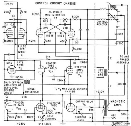
Used with two antennas on different parts of an aircraft to insert artificial delay in series with one antenna so signal addition will occur. Contains staircase generator that charges C1 in steps until receiver threshold cuts off V2. Charge on C1 biases V5 to change magnetization of reactor and thereby lock phaser automatically at optimum degree of delay.-I. Dlugatch, Optimizing Antenna Switches and Phasers, Electronics, 32:33, p 55-57. (View)
View full Circuit Diagram | Comments | Reading(596)
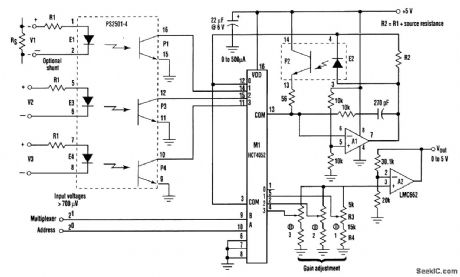
OPTICALLY_ISOLATED_ANALOG_MULTIPLEXER_
Published:2009/7/20 3:21:00 Author:Jessie

The circuit described here provides three channels of optically isolated input that will work for many precision signal-acquisition applications. The only power required is a single 15-V rail with ground common to the analog-to-digital converter. Multiplexer operation is based on an ordinary quad-channel optoisolator (PS2501-4). Each LED (such as E1) in combination with input-scaling resistor R1 will, in response to Vin, pass a current of I1=( Vin- VLED)/(R1+Rs), where VLED-the forward voltage drop of the LED and Rs=the signal source's internal resistance. R1 is chosen to establish a full-scale LED current near 500 μA. Assuming (for example) that channel 1 is selected, the resulting photocurrent in P1 will tend to pull the summing point of A1 low. In response, A1 will forward-bias E2 to generate a balancing photocurrent in P2. The E2 current required to maintain this balance will closely track I1, and the VLED of E2 will be close to the VLED of E1. The current sourced through M1 to the gain-adjustment network is directly proportional to the floating input voltages. Therefore, it is independent of the LED voltage drops. (View)
View full Circuit Diagram | Comments | Reading(2809)
FM_stereo_demodulator_with_stereo_monaural_switch_and_audio_muting
Published:2009/7/20 3:18:00 Author:Jessie
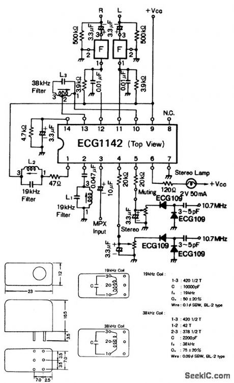
FM stereo demodulator with stereo-monaural switch and audio muting. Recommended supply voltage is 9 volts. Standby current is 10 mA. Input impedance is 20K. Audio muting is on at 0.85 volt and off at 1.08 volts. Stereo indicator is on at input voltage of 12 mV RMS and off at input voltage of 8.4mV RMS. Stereo-monaural switching occurs at 1.13 volts for stereo and 0.82 volt for monaural. Component F is a 38 kHz band eliminate filter (courtesy GTE Sylvania Incorporated). (View)
View full Circuit Diagram | Comments | Reading(575)
FM_detector_and_limiter_stage_for_45_MHz_or_107_MHz
Published:2009/7/20 3:17:00 Author:Jessie
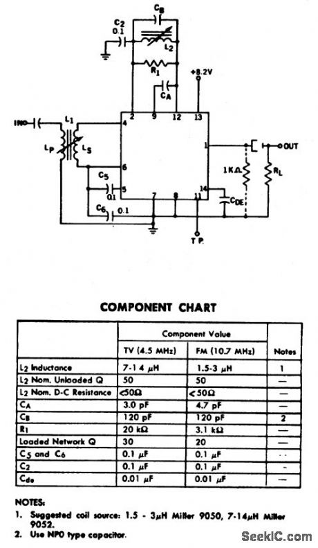
FM detector and limiter stage for 4.5 MHz or 10.7 MHz.using one ECG709. See component chart for appropriate frequency. Designed for use with an 8-volt supply, the ECG709 is a three-stage limiter with a balanced product detector. There are 19 transistors, 6 diodes, and 18 resistors inside the chip. Only one screw driver adjustment is necessary to tune the circuit (courtesy of GTE Sylvania Incorporated). (View)
View full Circuit Diagram | Comments | Reading(702)
CONTINUOUS_PHASE_CONTROL
Published:2009/7/20 3:16:00 Author:Jessie
Potentiometer changes phase relationship between synchronizing voltage V1 and output voltage V2, without affecting amplitude of output from free-running mvbr.-S. Tesic, Multivibrator Provides Continuous Phase Control, Electronics, 39:15, p 102-103. (View)
View full Circuit Diagram | Comments | Reading(614)
The warping machine auto control energy-saver
Published:2011/7/22 20:38:00 Author:qqtang | Keyword: warping machine, auto control, energy-saver
The working principle of the circuitThe warping machine auto control energy-saver consists of the light control circuit, magnetic control circuit, +5V power supply circuit and motor main control circuit, see as figure 8-134.
The light control circuit consists of the resistor RG, resistor R1, electric switch integrated circuit IC1, relay K1, filtering capacitor CI, rectifier bridge pile UR1 and power supply transformer T1. (View)
View full Circuit Diagram | Comments | Reading(1452)
OP_AMP_TESTER
Published:2009/7/20 3:15:00 Author:Jessie
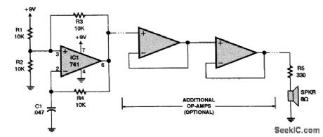
The circuit is a simple dead or alive test for an op amp. It is an oscillator that produces a 1500-Hz square wave, audible as a tone in the speaker. By looking at the output with an oscilloscope, you can measure the rise time. Several op amps can be tested at once by cascading them, as shown in the diagram. (View)
View full Circuit Diagram | Comments | Reading(1446)
Audio_amplifier_for_tape_recorder_using_an_EGG1043_14_pin_DIP
Published:2009/7/20 3:15:00 Author:Jessie
Audio amplifier for tape recorder using an EGG1043 14-pin DIP. Recommended supply voltage is 6 volts. Typical voltage gain is 85 dB. This circuit has an input impedance of 22K (courtesy GTE Sylvania Incorporated). (View)
View full Circuit Diagram | Comments | Reading(549)
AUDIO_CONTROL_FOR_ANTENNA_PHASER
Published:2009/7/20 3:15:00 Author:Jessie
Rectified audio in multiple-antenna aircraft receiver alternately charges C2 and C3 at grids of V2. Bistable mvbr V3 performs switching in synchronism with pulse generator so each switch position corresponds to change in antenna phasing. When peak of signal is passed and phase is reversed, V4 pulls in K1 and sends control signal to control unit. K2 opens when difference in potentials of C2 and C3 becomes excessive, forcing system to resume cycling until output is again maximized.-I. Dlugatch, Optimizing Antenna Switches and Phasers, Electronics, 32:33, p 55-57. (View)
View full Circuit Diagram | Comments | Reading(609)
OP_AMP_DC_OVERALL_FEEDBACK
Published:2009/7/20 3:15:00 Author:Jessie
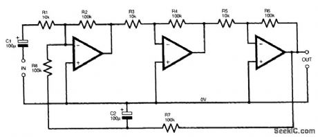
Overall dc feedback stabilizes the whole amplifier. (View)
View full Circuit Diagram | Comments | Reading(501)
| Pages:872/2234 At 20861862863864865866867868869870871872873874875876877878879880Under 20 |
Circuit Categories
power supply circuit
Amplifier Circuit
Basic Circuit
LED and Light Circuit
Sensor Circuit
Signal Processing
Electrical Equipment Circuit
Control Circuit
Remote Control Circuit
A/D-D/A Converter Circuit
Audio Circuit
Measuring and Test Circuit
Communication Circuit
Computer-Related Circuit
555 Circuit
Automotive Circuit
Repairing Circuit