LED and Light Circuit
DELAYED_SWEEP_ADAPTER
Published:2009/7/20 3:26:00 Author:Jessie | From:SeekIC

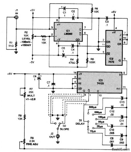
The schematic for the delayed sweep adapter is shown in the figure. Power for the circuit is pro-vided by a dual-polarity, 5-V supply. An LM360 high-speed comparator (IC1) with complementary TTL outputs is at the heart of the circuit. A trigger-level control, potentiometer R2, allows the adapter to trigger on any part of the waveform being displayed. With the values shown, the circuit functions well with a Hitachi V-212 oscilloscope, whose channel 1 output is about 25 mV per vertical division of the signal display. Assuming a normal display of about six divisions, the level control pro-vides a range of ±150 mV. You can change that range to suit your scope output by adjusting the ratio of R3 (15,000 Ω) to R4 (470 Ω); however, maintain the ratio of R5 (100,000 Ω) to R4 (470 Ω) for proper hysteresis. Resistor R1 (51 Ω) terminates the 50-Ω cable from the channel 1 output jack. IC2, a 7473 TTL dual J/K flip-flop, is configured in its toggle mode to divide the input frequency by 2. That ensures that IC3, a 74121 TTL monostable multivibrator, will function accurately over the in-put waveform's full time period. The pulse output from IC3 is coupled to the trigger-input jack of your oscilloscope, and the slope is selected via S2 to match the slope selected on your oscilloscope. Po-tentiometer R9 allows fine positioning of the trace and potentiometer R7 allows the output pulse width selected to be multiplied by a factor from x1 to over x2.5. Switch S1 lets you select the de-sired pulse width by switching in C8 through C13, in a 1-2-5 sequence. The adapter circuit was de-signed to operate on an external ±5-V, 100-mA power supply to avoid 60-Hz pickup in the unit.
Reprinted Url Of This Article:
http://www.seekic.com/circuit_diagram/LED_and_Light_Circuit/DELAYED_SWEEP_ADAPTER.html
Print this Page | Comments | Reading(3)

Article Categories
power supply circuit
Amplifier Circuit
Basic Circuit
LED and Light Circuit
Sensor Circuit
Signal Processing
Electrical Equipment Circuit
Control Circuit
Remote Control Circuit
A/D-D/A Converter Circuit
Audio Circuit
Measuring and Test Circuit
Communication Circuit
Computer-Related Circuit
555 Circuit
Automotive Circuit
Repairing Circuit
Code: