
Circuit Diagram
Index 874
HIGH_CURRENT_REGULATOR
Published:2009/7/20 3:01:00 Author:Jessie
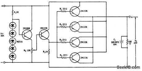
Four parallel-connected transistors handle up to 240 w if mounted with heat sink. If output voltage is reduced, separate power supply must be provided for zener regulator to protect transistors.- Zener Diode Handbook, International Rectifier Corp., 1960, p 57. (View)
View full Circuit Diagram | Comments | Reading(1200)
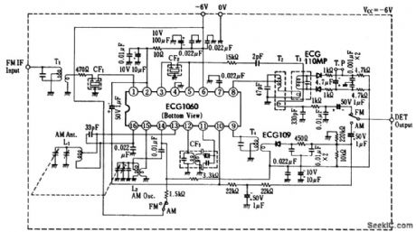
AM_FM_IF_amplifier_and_detector_using_an_ECG1108_14_pin_DIP
Published:2009/7/20 3:01:00 Author:Jessie
AM/FM IF amplifier and detector using an ECG1108 14-pin DIP. This chip is composed of three major sections. The input signal is fed to pin 14, then amplified by four-transistors. AGC is applied to pin 12. Output from this section is at pin 11. The next section receives its input at pin 8. This section is an AM IF and detector as well as an FM IF and Iimiter. The last section is an audio amplifier with its input at pin 2; output is from pin 3. Typical supply voltage is 5 volts (courtesy GTE Sylvania Incorporated). (View)
View full Circuit Diagram | Comments | Reading(776)
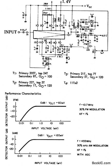
AM_receiver_front_end_with_AM_FM_IF_amplifier_detector_circuit
Published:2009/7/20 3:01:00 Author:Jessie
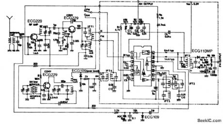
AM receiver front end with AM/FM IF amplifier-detector circuit. FM IF is 10.7 MHz,and the AM IF is 455 kHz.Detector output in FM is between 17 and 76 mV;for AM it is between 14.5 and 42 mV.All coils,transformers,variable capacitor and ceramic filters are standard and can be purchased at Radio Shack(courtesy GTE Sylvania Incorporated). (View)
View full Circuit Diagram | Comments | Reading(4367)
MUSIC_VISION_CIRCUIT
Published:2009/7/20 3:00:00 Author:Jessie
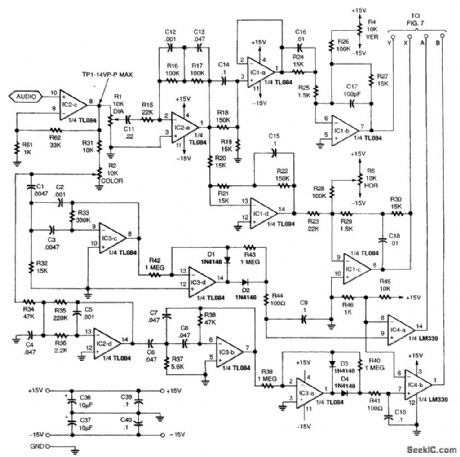
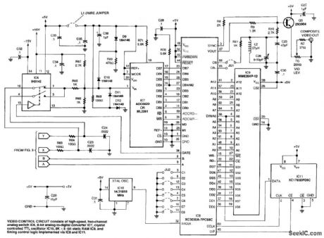
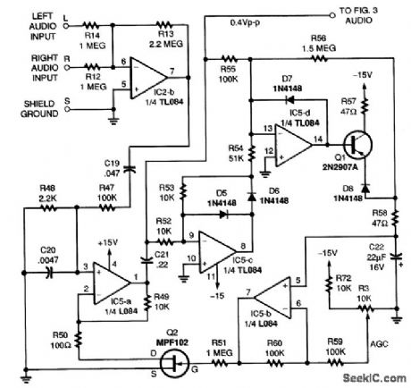
The basic concept involves processing an audio signal input into two components (x and y) that are phase-shifted approximately 90° relative to each other. The signals are then digitally sampled and stored in a video RAM buffer as an array of data bits. Bit locations in RAM correspond with the horizontal(x value) and vertical (y value) positions of points to be illuminated on the TV screen. The video RAM is periodically read and erased in synchronism with video frame scanning. The resulting serial video data is combined with color burst and sync signals to generate an NTSC-compatible composite video output signal. The music vision circuit essentially converts the standard raster-scanned TV screen into an oscilloscope-type display in which horizontal and vertical positions are directly controlled by z and y signals. The 90° phase shift between the two signals generates complex and dynamic two-dimensional patterns on the TV screen when music, voice, or other audio signals are applied to the input. The audio-frequency content of the input signal determines the color of the video pattern being displayed. (View)
View full Circuit Diagram | Comments | Reading(2209)
MAGNETICAMPLIFIER_REGULATOR
Published:2009/7/20 3:00:00 Author:Jessie
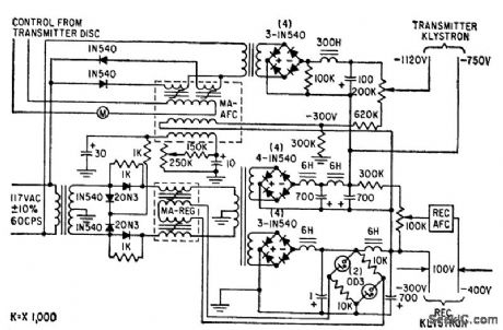
Provides stable operating voltages for transmitter and receiver local-oscillator klystrons in 6,000- Mc microwave link.-M. C. Harp, Nonvacuum Devices Control Klystrons, Electronics 32:7, p 68-70. (View)
View full Circuit Diagram | Comments | Reading(1025)
1_watt_audio_power_amplifier_using_an_ECG1033
Published:2009/7/20 2:59:00 Author:Jessie
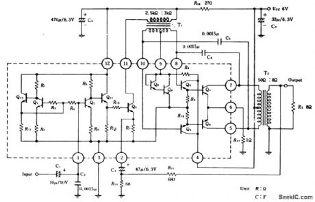
1-watt audio power amplifier using an ECG1033. Supply voltage is 6 volts. Typical voltage gain at 1 kHz is 47 dB. Packaging for the ECG1033 is a 12-pin plastic pack with metal tabs (courtesy GTE Sylvania Incorporated). (View)
View full Circuit Diagram | Comments | Reading(712)
6_V_D_C_REGULATOR
Published:2009/7/20 2:59:00 Author:Jessie
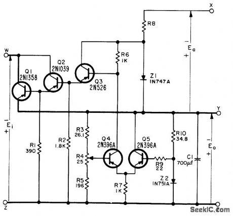
Provides 4 amp at 6 v with 1% regulation for inputs of 7 to 50 v from unregulated source. Auxiliary source Ea must be minimum of 5 v.-NBS, Handbook Preferred Circuits Navy Aeronautical Electronic Equipment, Vo1. 11, Semiconductor Device Circuits, PSC 1, p 1-2. (View)
View full Circuit Diagram | Comments | Reading(773)
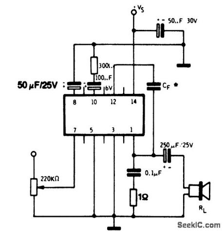
8_watt_AF_power_amplifier_for_8_ohm_or_4_ohm_speaker_load
Published:2009/7/20 2:53:00 Author:Jessie
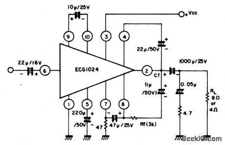
8-watt AF power amplifier for 8-ohm or 4-ohm speaker load. Typical supply voltage is 25 volts (courtesy GTE Sylvania Incorporated). (View)
View full Circuit Diagram | Comments | Reading(698)
Complete_167_MHz_IF_strip_for_an_FM_tuner_using_four_ECG703A_chips
Published:2009/7/20 2:53:00 Author:Jessie
Complete 16.7 MHz IF strip for an FM tuner using four ECG703A chips(courtesy GTE Sylvania Incorporated). (View)
View full Circuit Diagram | Comments | Reading(603)
COR_FOR_LINKING
Published:2009/7/20 2:52:00 Author:Jessie
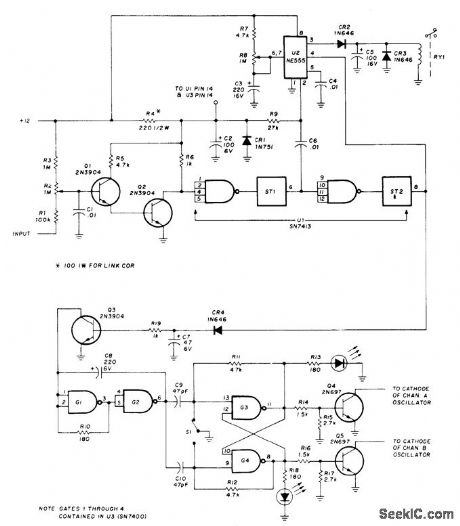
Carrier-operated relay will operate repeater, serve as guard receiver for repeater input channels, and provide loudspeaker muting when no station is being received Simple search-lock feature following CR4 controls two channels, for linking two repeaters or using two-channel drive receiver. Q1 and Q2 are connected as Darlington amplifier for negative-going control signals, as found in vacuum-tube receivers. Dual Schmitt trigger U1 provides positive ON/OFF action. Time-out is controlled by setting of R8 and value of Q3. To monitor repeater or simplex channel for call without listening to other conversations, set timer for about 5 s. When call comes in, first few words will be at normal volume so call can be identified. At time-out, volume will drop to low level. If call is for you, disable COR for normal listening. Search-lock uses single SN7400, with gates G1 and G2 connected as oscillator and gates 63 and 64 as dual D flip-flop. Q3 acts as lock to stop oscillator. With no input carrier, Q3 is off and oscillator makes Q4 and Q5 switch between channels A and B alternately. If signal arrives on one channel, oscillator stops on it and relay closes, bringing repeater transmitter on.-R. C. Heptig and R. D. Shriner, Carrier-Operated Relay for Repeater Linking, Ham Radio, July 1976, p 57-59. (View)
View full Circuit Diagram | Comments | Reading(3340)
FSK_DATA_RECEIVER
Published:2009/7/9 22:24:00 Author:May
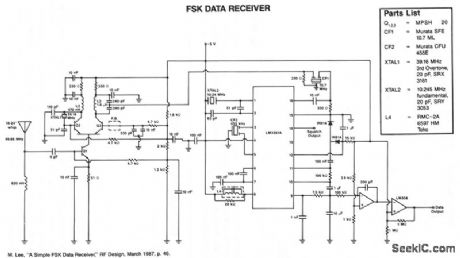
The various signal frequencies are obtained for an incoming carrier centered at 49.86 MHz. The receiver employs double conversion, with i-fs at 10.7 MHz and 455 kHz. Ceramic filters are used in both i-fs for selectivity and reduced-coil count. A quadrature detector is used to recover the baseband data, and an integrator and Schmitt trigger are used to filter the demodulated output.Also included is a squelch curcutt that functions as a status line, and the open-collector output switches high when a sianaHs received. The LM3361A functions as the 2nd LO, 2nd mixer, limiting i-f, quadrature detector, and squelch; yet, it consumes less than 4 mA from a 5-V logic supply. The entire receiver requires approximately 10 mA. (View)
View full Circuit Diagram | Comments | Reading(1324)
4_watt_AF_power_amplifiers_for_low_cost_record_players_using_an_ECG1111_14_pin_DIP
Published:2009/7/20 2:52:00 Author:Jessie
4-watt AF power amplifiers for low-cost record players using an ECG1111 14-pin DIP. The amplifier is designed to drive a 16-ohm load. Recommended supply voltage is 24 volts. Typical voltage gain is 74 dB. Input impedance is 110K, Capacitor CF can be either 510 pF or 820 pF, depending on the frequency response desired. For 510 pF the frequency response extends beyond 10 kHz. With CF at 820 pF the response falls off at about 8 kHz (courtesy GTE Sylvania Incorporated). (View)
View full Circuit Diagram | Comments | Reading(601)
LOGIC_LEVEL_TRANSLATORS
Published:2009/7/9 22:23:00 Author:May
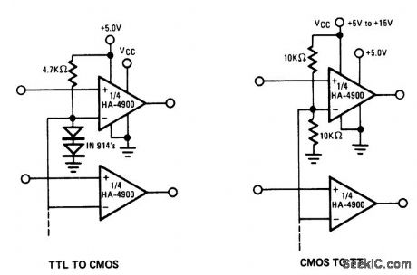
The HA-4900 senes comparators can be used as versatile logic interface devices,as shown in these circuits.Negative logic devices can also be interfaced with appropriate supply connections.If separatesupplies are used for V-and VLOGIC-,these logic-level translators will tolerate several volts of groundline differential noise. (View)
View full Circuit Diagram | Comments | Reading(1043)
FM_IF_amplifier_for_107_MHz
Published:2009/7/20 2:51:00 Author:Jessie
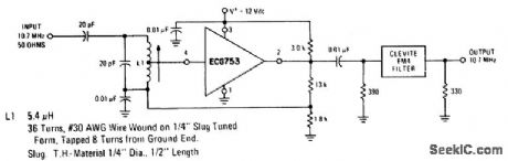
FM IF amplifier for 10.7 MHz (courtesy GTE Sylvania Incorporated). (View)
View full Circuit Diagram | Comments | Reading(604)
LOW_COST_LINE_RECEIVER
Published:2009/7/9 22:21:00 Author:May
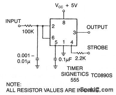
This timer makes an excellent line receiver for control applications involving relatively slow electromechanical devices. It can work without special drivers over single, unshielded lines. (View)
View full Circuit Diagram | Comments | Reading(1065)
FM_limiting_amplifier_and_Foster_Seeley_discriminator_designed_for_a_107_MHz_IF
Published:2009/7/20 2:51:00 Author:Jessie
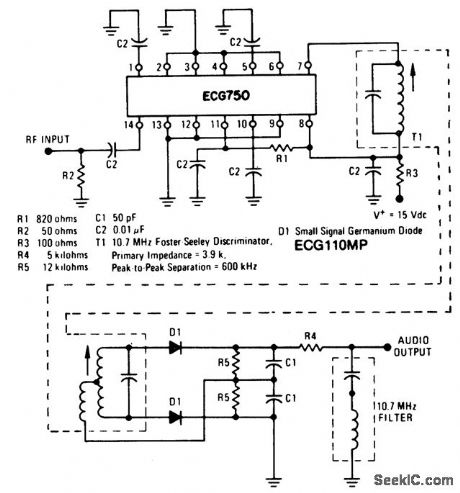
FM limiting amplifier and Foster-Seeley discriminator designed for a 10.7 MHz IF(courtesy GTE Sylvania Incorporated). (View)
View full Circuit Diagram | Comments | Reading(1015)
MULTIPLEXED_COMMON_CATHODE_LED_DISPLAY_ADC
Published:2009/7/9 22:20:00 Author:May
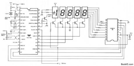
Here, a Teledyne TSC7135 DVM chip is used to drive a multiplexed 5-digit display. A CD4513BE CMOS IC, for common cathode drive, is used as a segment driver selected by pins 17-20 of the DVM chip. The transistors can be any suitable npn type such as 2N3904, etc. (View)
View full Circuit Diagram | Comments | Reading(2100)
AM_FM_radio_receiver_without_AF_amplifier_using_an_ECG1003_AM_FM_IF_amplifier
Published:2009/7/20 2:49:00 Author:Jessie


AM/FM radio receiver without AF amplifier using an ECG1003 AM/FM IF amplifier.AM specifications at 1000 kHz are:max sensitivity,26 dB/m;available sensitivity,44.5 dB/m;selectivity,+10 kHz 23 dB,-10 kHz 24 dB.FM specifications at 83 MHz are:max sensitivity,-1 dB PμV;available sensitivity,4.0 dB/μV;-3dB limiting sensitivity,12 dB/m;HFM availdable sensitivity,20dB/μV;3 dB bandwidth,200 kHz;demodulated output,60 mV(courtesy GTE Sylvania Incorporated). (View)
View full Circuit Diagram | Comments | Reading(2862)
LOW_LEVEL_POWER_FET_DRIVER_METHOD
Published:2009/7/9 22:20:00 Author:May
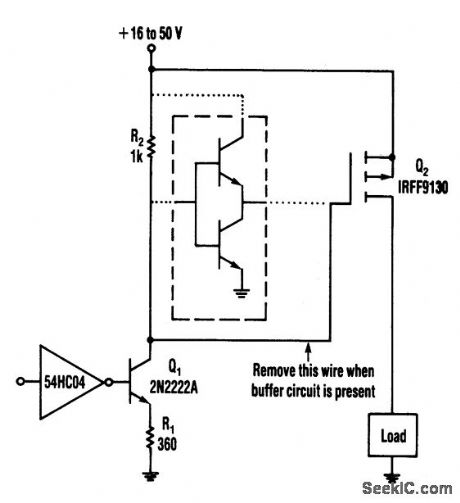
This circuit operates from a 16-to 50-V supply.Adding the buffer circuit(within the dashed lines)offers 100-ns switching times,Otherwise,the circuit switches in 1μs
Q1 and R1 form a switched current source of about 12 mA.The current flows through R2,whichsupplies 12V to the FET.The circuit works well,over a wide range of supply voltages,Furthermore,it switches smoothly in the presence of large ripple and noise on the supply. The switching time(about 1μs)can be reduced considerably by lowering the values of R1 and R2 at the expense of higher power dissipa-tions h the resistors and Q1.Alternatively,a buffer circuit can be added to produce switching times of 100ns without generatmg significant power dissipation. (View)
View full Circuit Diagram | Comments | Reading(778)
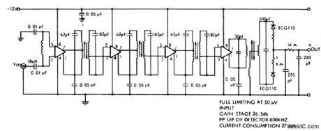
NARROW_BAND_FM_RECEIVER
Published:2009/7/9 22:19:00 Author:May
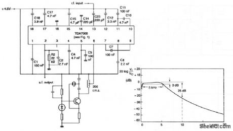
The local oscillator is crystal-controlled and the i-f swing is hardly compressed. The deviation of the transmitted carrier frequency, because of modulation, must therefore be limited to prevent severe distor-tion of the demodulated audio signal. The component values result in an i-f of 4.5 kHz and an i-f bandwidth of 5 kHz. If the i-f is multiplied by N, the values of capacitors C17 and C18 in the all-pass filters, and the values of filter capacitors C7, C8, C10, C11, and C12 must be multiplied by 1/N. For improved i-f selectivity to achieve greater adjacent channel attenuation, second-order networks can be used in place of C10 and C11. (View)
View full Circuit Diagram | Comments | Reading(940)
| Pages:874/2234 At 20861862863864865866867868869870871872873874875876877878879880Under 20 |
Circuit Categories
power supply circuit
Amplifier Circuit
Basic Circuit
LED and Light Circuit
Sensor Circuit
Signal Processing
Electrical Equipment Circuit
Control Circuit
Remote Control Circuit
A/D-D/A Converter Circuit
Audio Circuit
Measuring and Test Circuit
Communication Circuit
Computer-Related Circuit
555 Circuit
Automotive Circuit
Repairing Circuit