Audio Circuit
MUSIC_VISION_CIRCUIT
Published:2009/7/20 3:00:00 Author:Jessie | From:SeekIC


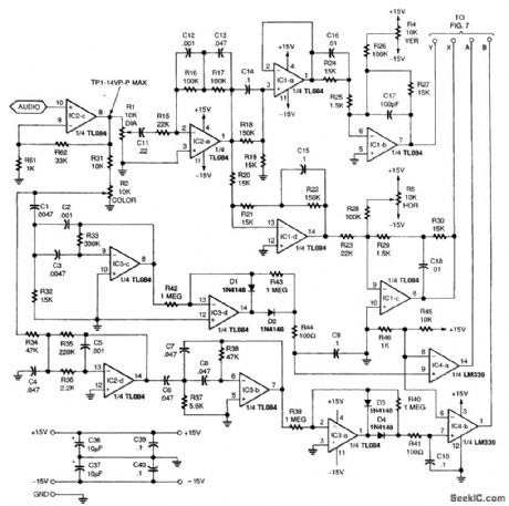
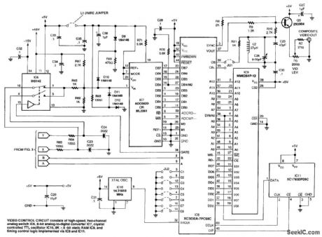
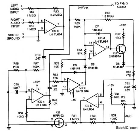
The basic concept involves processing an audio signal input into two components (x and y) that are phase-shifted approximately 90° relative to each other. The signals are then digitally sampled and stored in a video RAM buffer as an array of data bits. Bit locations in RAM correspond with the horizontal(x value) and vertical (y value) positions of points to be illuminated on the TV screen. The video RAM is periodically read and erased in synchronism with video frame scanning. The resulting serial video data is combined with color burst and sync signals to generate an NTSC-compatible composite video output signal. The music vision circuit essentially converts the standard raster-scanned TV screen into an oscilloscope-type display in which horizontal and vertical positions are directly controlled by z and y signals. The 90° phase shift between the two signals generates complex and dynamic two-dimensional patterns on the TV screen when music, voice, or other audio signals are applied to the input. The audio-frequency content of the input signal determines the color of the video pattern being displayed.
Reprinted Url Of This Article:
http://www.seekic.com/circuit_diagram/Audio_Circuit/MUSIC_VISION_CIRCUIT.html
Print this Page | Comments | Reading(3)

Article Categories
power supply circuit
Amplifier Circuit
Basic Circuit
LED and Light Circuit
Sensor Circuit
Signal Processing
Electrical Equipment Circuit
Control Circuit
Remote Control Circuit
A/D-D/A Converter Circuit
Audio Circuit
Measuring and Test Circuit
Communication Circuit
Computer-Related Circuit
555 Circuit
Automotive Circuit
Repairing Circuit
Code: