
Circuit Diagram
Index 871
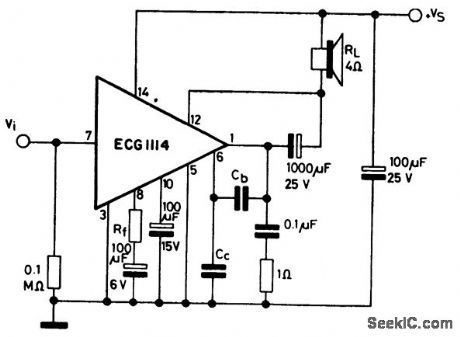
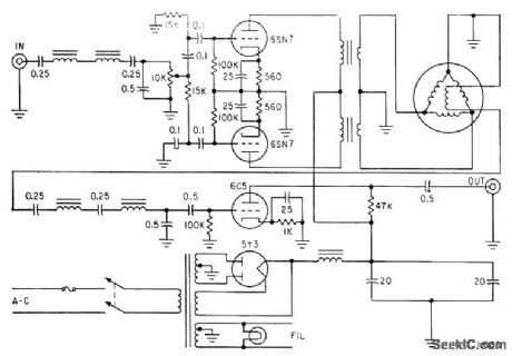
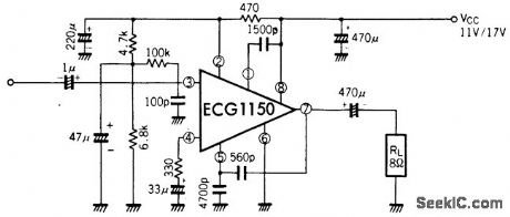
45_watt_AF_power_amplifier_with_grounded_load_for_radio_and_TV
Published:2009/7/20 3:41:00 Author:Jessie
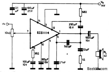
4.5-watt AF power amplifier with grounded load for radio and TV. The ECG1114 is a 14-pin QIP. Current drain at maximum output is 485 mA. Typical voltage gain is 46 dB. Input impedance is 3M (courtesy GTE Sylvania Incorporated). (View)
View full Circuit Diagram | Comments | Reading(564)
Bipolar_offset_binary_digital_to_voltage_converter_using_an_AD7520
Published:2009/7/20 3:41:00 Author:Jessie
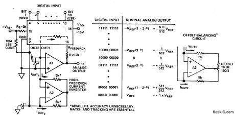
Bipolar offset-binary digital-to-voltage converter (four-quadrant multiplier) using an AD7520. R1 and R2 are used for gain adjustment (courtesy Analog Devices, Inc.). (View)
View full Circuit Diagram | Comments | Reading(1211)
Voltage_to_frequency_convener
Published:2009/7/20 3:40:00 Author:Jessie
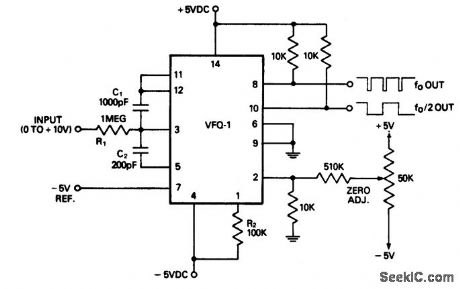
Voltage-to-frequency convener. Full scale frequency is 10 kHz as shown. The chip is the Datel VFQ-1 Not the fo output and fo/2 outputs. Full scale output can be extended to 100 kHz by changing C1 and C2 as indicated on schematic (courtesy Datel Systems, Inc.). (View)
View full Circuit Diagram | Comments | Reading(932)
10_kHz_frequency_to_voltage_convener
Published:2009/7/20 3:39:00 Author:Jessie
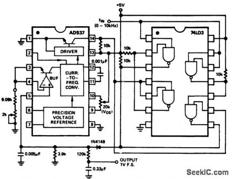
10 kHz frequency-to-voltage convener. The input signal should be a pulse train or square wave with characteristics similar to TTL or 5-volt CMOS outputs. Minimum pulse width is 40 μs. Full scale output is 1 volt for a 10kHz input. To trim first set Vos to midrange and trim the 2K pot for 1-volt output. Then apply a 10-hertz waveform and trim Vos for a 10 mV output (courtesy Analog Devices, Inc.). (View)
View full Circuit Diagram | Comments | Reading(1009)
Sign_magnitude_DIA_converter_with_BCD_coding
Published:2009/7/20 3:38:00 Author:Jessie
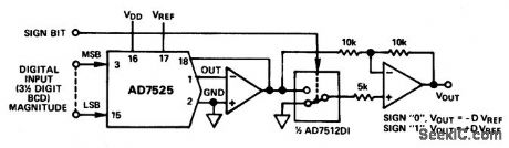
Sign-magnitude DIA converter with BCD coding. The AD7525 is used to provide a choice of positive or negative gains for the analog input signal, with sign-magnitude BVD coding. Gains range from -1.999 to +1.999. The BCD coding of the AD7525 permits it to be used with thumbwheel switches for manual gain setting without BCD-binary translation (courtesy Analog Devices, Inc.). (View)
View full Circuit Diagram | Comments | Reading(1103)
High_performance_RMS_to_DC_converter
Published:2009/7/20 3:36:00 Author:Jessie
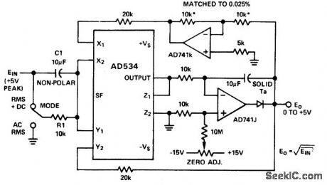
High-performance RMS-to-DC converter. To calibrate switch to RMS+DC,apply an input of say 1.00 volt DC and set the zero adjust until the output reads the same as the input.Check the inputs of ±5 volts(courtesy Analog Devices,Inc.). (View)
View full Circuit Diagram | Comments | Reading(1037)
7_watt_AF_power_amplifier_featuring_thermal_shutdown_with_load_connected_to_ground
Published:2009/7/20 3:36:00 Author:Jessie
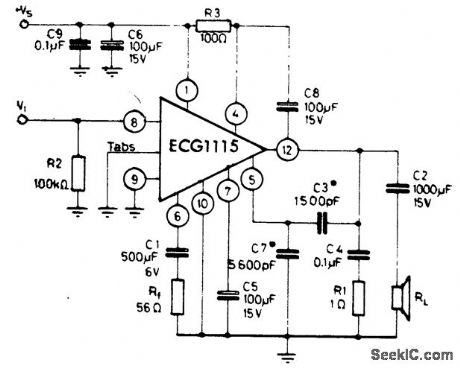
7-watt AF power amplifier featuring thermal shutdown with load connected to ground. For the rated output of 7 watts a 16-volt supply voltage is required. At a supply voltage of 9 volts the power output is 2.5 watts. Input voltage is 220 mV PMS. Input resistance is 5M. The ECG1115 is a 12-pin QIP with two metal tabs (courtesy GTE Sylvania Incorporated). (View)
View full Circuit Diagram | Comments | Reading(625)
45_watt_AF_power_amplifier_for_radio_and_TV
Published:2009/7/20 3:35:00 Author:Jessie
4.5-watt AF power amplifier for radio and TV. Recommended supply voltage is 14 volts. Current drain at maximum power output is 485 mA. Typical voltage gain is 46 dB. Input impedance is 3M (courtesy GTE Sylvania Incorporated). (View)
View full Circuit Diagram | Comments | Reading(501)
Picoampere_to_voltage_converter_with_gain
Published:2009/7/20 3:35:00 Author:Jessie
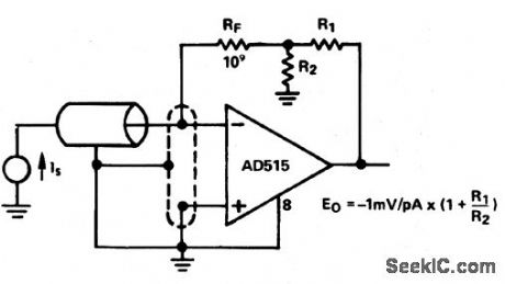
Picoampere-to-voltage converter with gain (courtesy Analog Devices, Inc.). (View)
View full Circuit Diagram | Comments | Reading(899)
Current_to_voltage_converter_with_grounded_bias_and_sensor
Published:2009/7/20 3:34:00 Author:Jessie
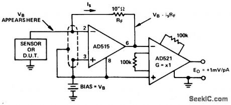
Current-to-voltage converter with grounded bias and sensor (courtesy Analog Devices, Inc.). (View)
View full Circuit Diagram | Comments | Reading(0)
PORTABLE_SCOPE_CALIBRATOR
Published:2009/7/20 3:33:00 Author:Jessie
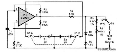
This simple circuit can be used to calibrate scopes or other equipment. (View)
View full Circuit Diagram | Comments | Reading(620)
High_speed_10_bit_A_D_converter_using_the_μA_722_and_an_ECG915_operational_amplifier
Published:2009/7/20 3:33:00 Author:Jessie
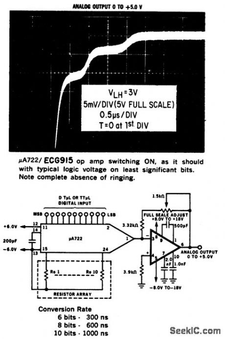
High-speed 10-bit A/D converter using the μA 722 and an ECG915 operational amplifier (courtesy GTE Sylvania Incorporated). (View)
View full Circuit Diagram | Comments | Reading(1019)
The automobile steering alarm (5)
Published:2011/7/22 21:50:00 Author:qqtang | Keyword: steering alarm
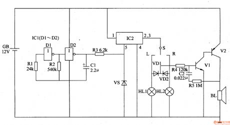
The working principle of the circuit The automobile steering alarm consists of the low-frequency oscillator, the electric switch circuit and the sound alarm circuit, see as figure 7-128.
The low-frequency oscillator consist of the NOR gate circuit ICl(Dl and D2), resistors of R1 and R2, capacitor C1 and so on. The electric switch circuit consists of the electric switch integrated circuit IC2, resistor and regulated diode VS. (View)
View full Circuit Diagram | Comments | Reading(417)
SELF_SYNCHRONIZED_PHASE_SHIFTER
Published:2009/7/20 3:32:00 Author:Jessie
Consists of power supply, inverter, phase-shifting Selsyn, 100-cps filter, and output amplifier, used to vary phase of 100-cps frequency standard output by synchronization with WWV for studies of low-frequency propagation over long distances.-M. M. Newman etal, Sea-Going Lightning Generator, Electronics, 33:30, p 53-55. (View)
View full Circuit Diagram | Comments | Reading(1072)
4_to_20_mA_converter
Published:2009/7/20 3:31:00 Author:Jessie
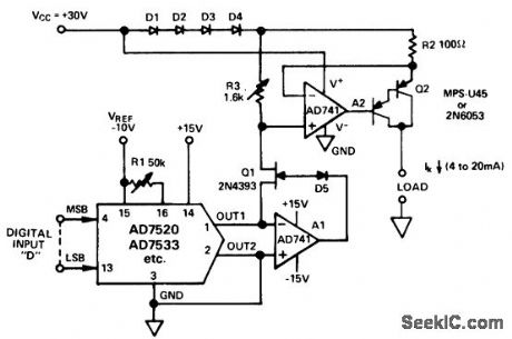
4 to 20 mA converter. The circuit drives a digitally programmed current into a grounded load, RL, according the the relationship IK 4mA (D) (16 mA). With a 10-bit D/A convener such as the AD7520 the circuit provides an output from 4 mA to 20 mA with a resolution of 155/8 μA. The maximum compliance voltage of the load is +25 volts, equivalent to a resistance of 1250 ohms maximum. Higher voltages across the load can be developed if the lower end of RL is returned to a negative voltage, but Q2 must be able to handle the additional breakdown voltage (courtesy Analog Devices, Inc.). (View)
View full Circuit Diagram | Comments | Reading(1564)
D_F_convener_with_complementary_output_frequencies
Published:2009/7/20 3:30:00 Author:Jessie
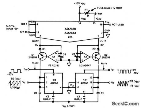
D/F convener with complementary output frequencies. This circuit provides two output frequencies. One output is proportional to the fractional binary equivalent of D, while the other output is proportional to 1 - D. Excellent linearity is obtained from 10 hertz to 10 kilohertz. The 556 timer provides either pulse or sawtooth output waveforms. D1 and D2 are required to protect the emitter-base junctions of Q1 and Q2 during power up. D3 and D4 protect the AD7520 OUT 1 and OUT 2 terminals (courtesy Analog Devices, Inc.). (View)
View full Circuit Diagram | Comments | Reading(1049)
25_watt_AF_power_amplifier
Published:2009/7/20 3:30:00 Author:Jessie
2.5-watt AF power amplifier. Recommended supply voltage is 17 volts. No-signal current is 24 mA. Input impedance is 85K (courtesy GTE Sylvania Incorporated). (View)
View full Circuit Diagram | Comments | Reading(480)
15_watt_2_watt_AF_power_amplifiers_using_an_ECG1141_1140_8_pin_DIP
Published:2009/7/20 3:29:00 Author:Jessie
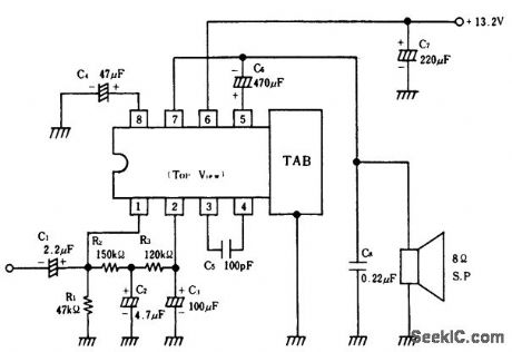
1.5-watt/2-watt AF power amplifiers using an ECG1141/1140 8-pin DIP. This amplifier is ideal for automotive applications since the recommended supply voltage is 13.2 volts. Typical voltage gain is between 51 and 56 dB. No signal supply current is 12 mA (courtesy GTE Sylvania Incorporated). (View)
View full Circuit Diagram | Comments | Reading(560)
FM_tuner_front_end_using_dual_gate_MOSFETs
Published:2009/7/20 3:28:00 Author:Jessie
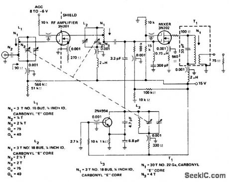
FM tuner front end using dual-gate MOSFETs (courtesy Texas Instruments Incorporated). (View)
View full Circuit Diagram | Comments | Reading(3416)
High_gain_AF_preamplifier_using_an_ECG1135_7_pin_module
Published:2009/7/20 3:28:00 Author:Jessie
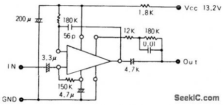
High-gain AF preamplifier using an ECG1135 7-pin module. This circuit is ideal for automotive stereo applications. No-signal supply current is 1.5 mA. Input impedance is 120K, while output impedance is 5 ohms (courtesy GTE Sylvania Incorporated). (View)
View full Circuit Diagram | Comments | Reading(472)
| Pages:871/2234 At 20861862863864865866867868869870871872873874875876877878879880Under 20 |
Circuit Categories
power supply circuit
Amplifier Circuit
Basic Circuit
LED and Light Circuit
Sensor Circuit
Signal Processing
Electrical Equipment Circuit
Control Circuit
Remote Control Circuit
A/D-D/A Converter Circuit
Audio Circuit
Measuring and Test Circuit
Communication Circuit
Computer-Related Circuit
555 Circuit
Automotive Circuit
Repairing Circuit