
Circuit Diagram
Index 865
LIGHT_ACTIVATED_MOTOR_DRIVE_CIRCUIT
Published:2009/7/20 2:38:00 Author:Jessie
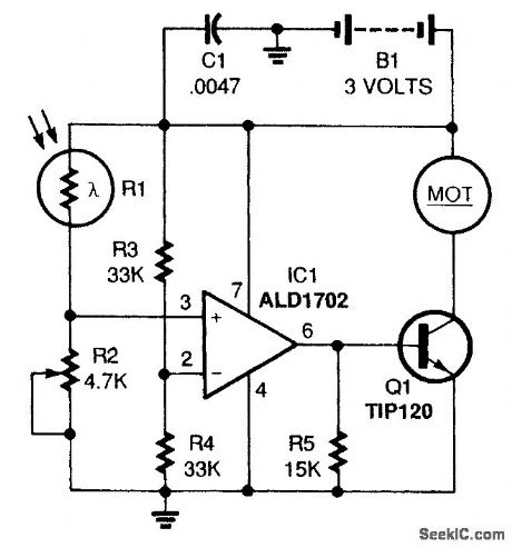
The circuit is a basic light-activated on/off switch for the motor. A CMOS op amp (IC1) is used as a voltage comparator. The comparator monitors the levels of two input voltages and switches its out-put on or off, depending on which input voltage is greater. The input on pin 2 is set to a reference voltage of about half the supply voltage by R3 and R4. The input on pin 3 is connected to a voltage divider made up of a cadmium sulfide photocell (R1) and potentiometer R2. The resistance of a photocell changes depending upon the amount of light shining on it, so the intensity of light is indicated by the voltage on pin 3 of IC1. The light level at which the circuit turns on is adjusted by R2. When the voltage on pin 3 of IC1 is greater than that on pin 2, the output (pin 6) turns on. The output of IC1 drives Q1 directly. That transistor acts like a current amplifier for the op amp. The transistor switches the motor on and off. (View)
View full Circuit Diagram | Comments | Reading(1194)
TRIP_WIRE_ALARM
Published:2009/7/9 23:13:00 Author:May
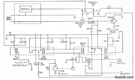
Control circuit tums converter, transmitter, and modulator on through relay contacts, to make 1,680-kc hybrid transmitter send tone-modukned signals to central station when trip wire is broken by ava lanche. Daylight on photocell initiates test transmission dcdly.-G.Neal and S. A. Stone, Hybrid Telemeter Detects Avalanches, Electtonics, 34:50, p 72-73.
(View)
View full Circuit Diagram | Comments | Reading(833)
FET_VOLTMETER_1
Published:2009/7/9 23:13:00 Author:May
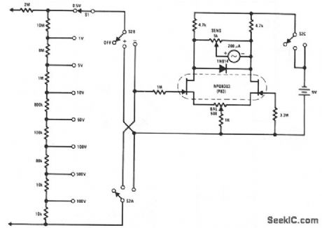
This FETVM replaces the function of the VTVM and rids the instrument of the usual line cord. In addition, FET drift rates are far superior to vacuum tube circuits, allowing a 0.5 V full-scale range which is impractical with most vacuum tubes. The low leakage, low noise NPD8303 is ideal for this application. (View)
View full Circuit Diagram | Comments | Reading(2120)
2_watts_per_channel_dual_audio_amplifier_using_an_ECG804_IC
Published:2009/7/20 2:38:00 Author:Jessie
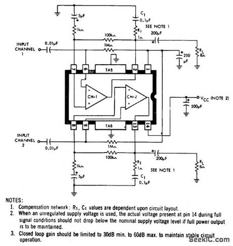
2-watts-per-channel dual audio amplifier using an ECG804 IC. For 8-ohmspeaker loads use a 20-volt supply, for 16-ohm sneaker loads use a 24-voltsupplyand for 4.ohm speaker loads use a 12-volt supply (courtesy GTE Sylvania Incorporated). (View)
View full Circuit Diagram | Comments | Reading(529)
SAMPLE_AND_HOLD_1
Published:2009/7/9 23:13:00 Author:May
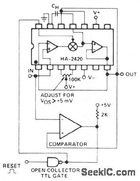
The sample-and-hold function has often been accomplished with separate analog switches and op amps. These designs always involve performance tradeoffs between acquisition time, charge injection, and droop rate. The HA-242-/2425 monolithic sample-and-hold, has many better tradeoffs, and usually a lower total cost than the other ap-proaches. The switching element is a complementary bipolar circuit with feedback, which allows high charging currents of 30 mA, a low charge injection of 10 pC, and an ultra-low off leakage current of 5 pA; a combination that is not approached in any other electronic switch. These factors make it also superior as an integrator reset switch, or as a precision peak detector. (View)
View full Circuit Diagram | Comments | Reading(686)
FM_IF_amplifier_using_two_MC1355_chips
Published:2009/7/20 2:37:00 Author:Jessie
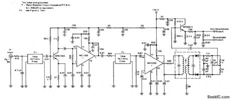
FM IF amplifier using two MC1355 chips. Two TRW phase linear five-pole 10.7 MHz filters provide a combined 240 kHz bandwidth (courtesy Motorola Semiconductor Products Inc.). (View)
View full Circuit Diagram | Comments | Reading(1031)
COMPRESSOR_PROTECTOR
Published:2009/7/9 23:13:00 Author:May
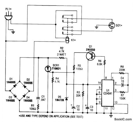
This circuit monitors the power-line (ac) voltage.When a power failure occurs,on restoration of power,the circuit adds a five-minute delay before energizing K1,which protects the compressor against limited low voltage.
U1 is a 16-stage counter with an integral oscillator that is set to divide by 8192. R7, R8, and C4 set the oscillator frequency to about 25 Hz, which produces a total count interval of 300 seconds (5Mnutes). After this time, pin 8 U1 goes high, which forward biases Q1,triggers SCR1,and activates K1. Up to 30 A can be switched.
(View)
View full Circuit Diagram | Comments | Reading(1724)
FUNCTION_DECODER
Published:2009/7/20 2:37:00 Author:Jessie
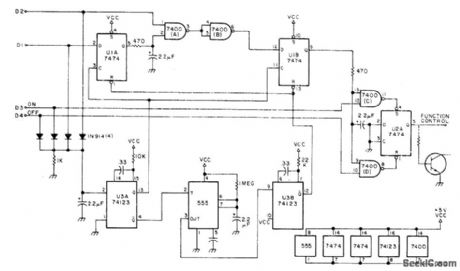
Simple controller for single repeater uses 3-digit control code (523) to turn repeater on and 524 to turn it off. Digits must be in correct sequence. Digit decoder (not shown) uses TTL-compatible inputs which go high when digit is decoded. Four 1N914 diodes form OR gate that triggers U3A to create clock pulse with each digit received. Other output of U3Atriggers 555timer U5, set for delay of about 8 s. At end of delay, timer triggers U3B to reset all logic except for output stage. Regulated VCC of 5 V is obtained from 7805 regulator connected to 12 V.-W. J. Hosking, Simple Sequential Decoder, 73 Magazine, Jan. 1978, p 166-167. (View)
View full Circuit Diagram | Comments | Reading(711)
ALARM_SYSTEM_CODER
Published:2009/7/9 23:12:00 Author:May

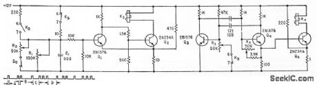
Used to generate zone codes for fire alarm.Multivibrator Q3-Q4 determines duration of A and B, while 01-02 delermines lime C-D. Molor-driven stepping switches (not shown) determine the number of K4 operations lo provide predetermined zone coding (zone 1213 for code group shown).-W. F. Ferguson, High-Powered Audio Alarm Systems, Electronics, 33:16, p 70-72. (View)
View full Circuit Diagram | Comments | Reading(556)
PM_DC_MOTOR_SPEED_CONTROL_
Published:2009/7/20 2:37:00 Author:Jessie
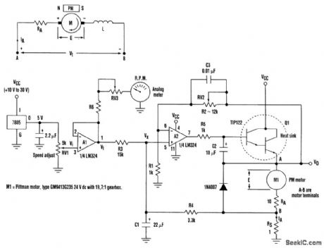
Speed control of permanent-magnet (PM) dc motors with the aid of optical or dc tachometers is generally inconvenient and difficult, particularly on motors with integral gearboxes. The high-speed shaft of the motor that drives the gearbox isn't always accessible and the speed of the geared-down shaft often is too low for tachometers. Described here is a single-supply regulating speed-control circuit that doesn't require a tachometer. It keeps the motor torque high under load by using positive feedback to compensate for the drop caused by armature resistance. In unregulated variable-speed PM dc motor systems, the drop in speed under load is particularly pronounced at low motor-supply voltages. The positive feedback generates a negative resistance that compensates for the nonlinear effects caused by armature resistance. It thereby ensures that the speed-control input voltage (Vi) linearly controls the speed of the motor. Armature resistance compensation is achieved if:
RS= RA/[gain(R3) / (R3 + R4)] - 1
The divider action of R3 and R4 together with the gain reduces the value required for Rs to minimize the power dissipation. C1 and R4 dampen the positive-feedback signal's response time, but they also form a low-pass filter and attenuate the motor current noise fed to the A2 input. The maximum output voltage swing from A2 is approximately VCC-2 V, and there is a 1.2-V Vbe loss by T1. This implies that the supply voltage (Vcc) should be about 5 V above the maximum desired motor voltage in order to allow for extra output drive to the motor under heavy load conditions. A reason-able choice for Rs is approximately RA/10, and the gain of A2 should be trimmed with RV2 to ensure that the motor's speed does not drop when loaded. (View)
View full Circuit Diagram | Comments | Reading(4050)
PRINTER_ERROR_ALARM
Published:2009/7/9 23:12:00 Author:May
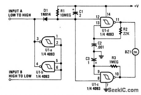
When a printer is shut down, this alarm sounds an alarm. The input can be either a high-to-low or low-to-high transition. This can be a logic level that corresponds with the printer being on or off. The oscillator produces an interrupted (on-off) tone. (View)
View full Circuit Diagram | Comments | Reading(728)
ZENER_REFERENCE
Published:2009/7/20 2:36:00 Author:Jessie
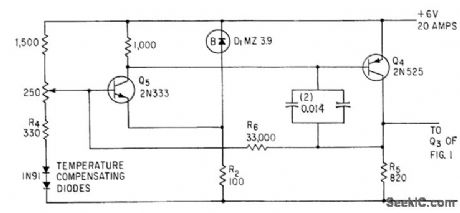
Sensing circuit for 6-v constant-voltage transformer -regulated power supply develops error signal for controlling shunt transistors.-J. T. Keefe, Transformer and Shunt Transistors Regulate D-C Power Supply, Electronics, 34:20, p 99:101. (View)
View full Circuit Diagram | Comments | Reading(502)
FILTERED_SAMPLE_AND_HOLD
Published:2009/7/9 23:12:00 Author:May
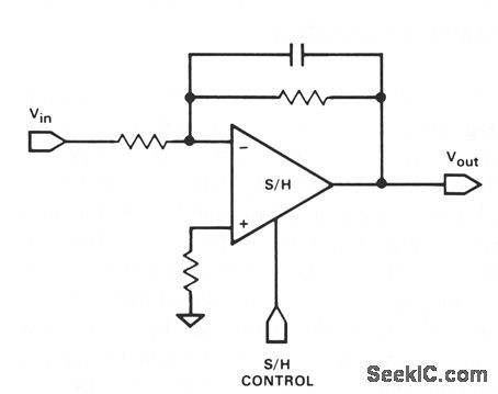
It is often required that a signal be filtered pnor to sampling. This can be accomplished with only one device. Use any of the inverting and noninverting filters that can be built with op amps. However, it is necessary that the sampling switch be closed for a sufficient time for the filter to settle when active filter types are connected around the device. (View)
View full Circuit Diagram | Comments | Reading(692)
Low_noise_AF_preamplifier
Published:2009/7/20 2:36:00 Author:Jessie
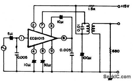
Low-noise AF preamplifier. The preamplifier provides 0.9 volts output at 1 kHz witha 2 mV input. ECG1015 is a hybrid module (courtesy GTE Sylvania Incorporated). (View)
View full Circuit Diagram | Comments | Reading(601)
HIGH_SPEED_SAMPLE_AND_HOLD
Published:2009/7/9 23:11:00 Author:May
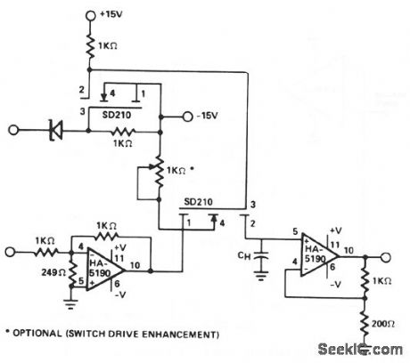
This circuit uses the speed and drive capability of the HA-5190 coupled with two high-speed DMOS FET switches. The input amplifier is allowed to operate at a gain of -5, although the overall circuit gain is unity. Acquisition times of less than 100 ns to 0.1% of a 1-V input step are possible. Drift current can be appreciably reduced by using FET input buffers on the output stage of the sample-and-hold. (View)
View full Circuit Diagram | Comments | Reading(0)
SIREN_PREAMPLI_FIER
Published:2009/7/9 23:11:00 Author:May
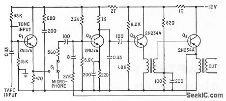
Supplies signals to remote power ampliters and loudspeakers of fire and civil defense systems. Input can be from electronic siren generator, magnetic tape, or microphone.-W. F. Ferguson, High-Powered Audio Alarm Systems, Electronics, 33:16, p 70-72. (View)
View full Circuit Diagram | Comments | Reading(612)
1800_Hz_TONE_BURST
Published:2009/7/20 2:35:00 Author:Jessie
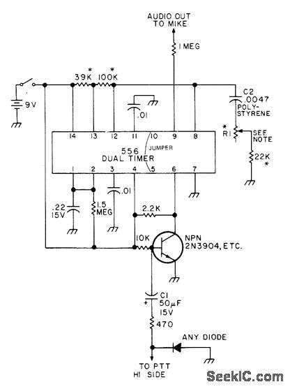
Developed to provide access to repeater requiring accurate tone frequency. Half of 556 dual timer serves as mono MVBR having 0N time of about 400 ms. Other half is free-running oscillator that is disabled when mono goes low. Transistor starts tone burst when push-to-talk switch is closed. For frequency stability, resistors with asterisk should be cermet or wirewound. R1 is 15- or 20-turn trimmer pot having low temperature coefficient and giving about 30 Hz change per turn.-L. Meyer, 0ne IC Tone Burster, 73 Magazine, April 1976, p 55. (View)
View full Circuit Diagram | Comments | Reading(753)
SWITCH_DEBOUNCER_WITH_AUTO_REPEAT
Published:2009/7/9 23:11:00 Author:May
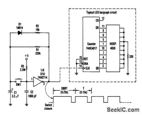
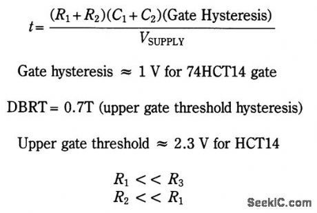
This circuit produces an output pulse when SW1 (pushbutton) is depressed. It also becomes a hysteresis gate oscillator. D1 and R2 add asymmetry. The DBRT (delay before repeat time) is caused by the oscillator start-up conditions: C1 has to change from zero to the upper gate threshold rather than to the lower threshold.
The auto repeat time:
(View)
View full Circuit Diagram | Comments | Reading(818)
RATE_OF_RISE_HEAT_ALARM_WITH_DELAY
Published:2009/7/9 23:09:00 Author:May
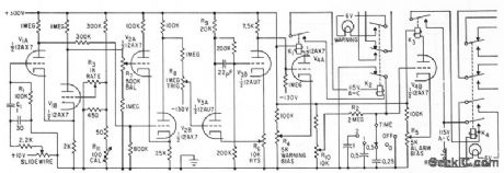
Thermocouple senses rise in temperature of machinery or heat of fire, and feeds servo null-balance recorder having repeater slide-wire. Output of slidewire is differentiated by C1-R1 and compared with reference rise rate voltctge at grid of V1B. When ampliled difference at output of V2 switches Schmitt trigger V3, V4A conducts and energizes K1.Additional triode and relays provide time delay for cdarm lamp.-T. L. Greenwood, Indicalor Warns of Excessive Rise Roles, Electronics, 35:7, p 54-56. (View)
View full Circuit Diagram | Comments | Reading(599)
MOTORCYCLE_INTERCOM
Published:2009/7/20 2:44:00 Author:Jessie
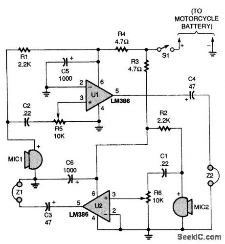
Why yell at your passenger when you can talk? Use this two-way intercom to make communicating on the open road a lot easier. (View)
View full Circuit Diagram | Comments | Reading(1859)
| Pages:865/2234 At 20861862863864865866867868869870871872873874875876877878879880Under 20 |
Circuit Categories
power supply circuit
Amplifier Circuit
Basic Circuit
LED and Light Circuit
Sensor Circuit
Signal Processing
Electrical Equipment Circuit
Control Circuit
Remote Control Circuit
A/D-D/A Converter Circuit
Audio Circuit
Measuring and Test Circuit
Communication Circuit
Computer-Related Circuit
555 Circuit
Automotive Circuit
Repairing Circuit