Measuring and Test Circuit
PEAK_PROGRAM_DETECTOR
Published:2009/7/9 23:22:00 Author:May | From:SeekIC

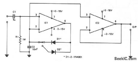
This circuit will allow a multimeter to display the positive or negative peaks of an incoming signal. A 741, IC1, is used in the noninverting mode with R1 defining the input impedance. D1 or D2 will conduct on a positive or negative peak, charging C2 until the inverting input is at the same dc level as the incoming peak. This level will maintain the voltage until a higher peak is detected, then this will be stored by C2. Another 741, IC2, prevents loading by the multimeter. Connected in the noninverting mode as a unity gain buffer, output impedance is less than 1 Ω. This circuit has a useful frequency response from 10 Hz to 100 kHz at ± 1 dB. High linearity is ensured by placing the diodes in the feedback loop of IC1, effectively compensating for the 0.6 V bias that these components require.
Reprinted Url Of This Article:
http://www.seekic.com/circuit_diagram/Measuring_and_Test_Circuit/PEAK_PROGRAM_DETECTOR.html
Print this Page | Comments | Reading(3)

Article Categories
power supply circuit
Amplifier Circuit
Basic Circuit
LED and Light Circuit
Sensor Circuit
Signal Processing
Electrical Equipment Circuit
Control Circuit
Remote Control Circuit
A/D-D/A Converter Circuit
Audio Circuit
Measuring and Test Circuit
Communication Circuit
Computer-Related Circuit
555 Circuit
Automotive Circuit
Repairing Circuit
Code: