Basic Circuit
TRACK_AND_HOLD_SAMPLE_AND_HOLD
Published:2009/7/9 23:27:00 Author:May | From:SeekIC

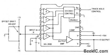
Channel 1 is wired as a voltage follower and is turned on during the track/sample time. If the product of R × C is sufficiently short compared to the period of maximum output frequency, or sample time; Cwill charge to the output level. Channel 2 is an integrator with zero input signal. When channel 2 is then turned on, the output will remain at the voltage across C.
Reprinted Url Of This Article:
http://www.seekic.com/circuit_diagram/Basic_Circuit/TRACK_AND_HOLD_SAMPLE_AND_HOLD.html
Print this Page | Comments | Reading(3)

Article Categories
power supply circuit
Amplifier Circuit
Basic Circuit
LED and Light Circuit
Sensor Circuit
Signal Processing
Electrical Equipment Circuit
Control Circuit
Remote Control Circuit
A/D-D/A Converter Circuit
Audio Circuit
Measuring and Test Circuit
Communication Circuit
Computer-Related Circuit
555 Circuit
Automotive Circuit
Repairing Circuit
Code: