Basic Circuit
TIME_OUT_WARNING_1
Published:2009/7/20 2:22:00 Author:Jessie | From:SeekIC

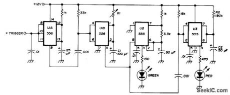
Transceiver-actuated circuit inhibits FM repeater timer override. Uses 556 dual timer and two 555 timers. Triggers on positive step-input voltage from transceiver when PTT switch is pushed. If negative triggering is preferred, omit U1A. Values of R1 and C1 provide delay that is 10 s less than repeater timer. With 60-s repeater, delay should be 50 s.Flip-flop U2 flashes green LED80times per minute during this delay. After 50 s, U2 is disabled and U3 flashes red LED for 10 s as indication that transmission must stop to avoid timing out repeater. At end of 10 s, red LED goes out and cycle is completed. If transmission time is less than that of repeater timer, indicator is recycled when PTT switch is pressed again. R1-C1 deter-mine green flash time, and R2-C2 determine red flash time.-H. M. Berlin, Time-Out Warning Indicator for FM Repeater Users, Ham Radio, June 1976, p 62-63.
Reprinted Url Of This Article:
http://www.seekic.com/circuit_diagram/Basic_Circuit/TIME_OUT_WARNING_1.html
Print this Page | Comments | Reading(3)

Article Categories
power supply circuit
Amplifier Circuit
Basic Circuit
LED and Light Circuit
Sensor Circuit
Signal Processing
Electrical Equipment Circuit
Control Circuit
Remote Control Circuit
A/D-D/A Converter Circuit
Audio Circuit
Measuring and Test Circuit
Communication Circuit
Computer-Related Circuit
555 Circuit
Automotive Circuit
Repairing Circuit
Code: