Amplifier Circuit
60_W_225-400_MHz_AMPLIFIER
Published:2009/7/9 23:06:00 Author:May | From:SeekIC

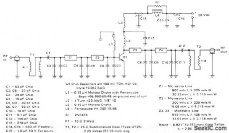
This 60-W, 28-V broadband amplifier covers the 225-400 MHz military communications band. The amplifier may be used singly as a 60-W output stage in a 225-400 MHz transmitter, or by using two of these amplifiers combined with quadrature couplers, a 100-W output amplifier stage can be constructed.The circuit is designed to be driven from a 50-Ω source and work into a nominal 50-Ω load. The input network consists of two microstrip L-sections composed of Z1, Z2, and C2 through CG. C1 serves as a dcblocking capacitor. A 4:1 impedance ratio coaxial transformer T1 completes the input matching network.L1 and a ferrite bead serve as a base decoupling choke. The output circuit consists of shunt inductor L2 at the collector, followed by two microstrip L-sections composed of Z3, Z4, and C8 through C11. C12 serves as a dc blocking capacitor, and is followed by another 4:1 impedance ratio coaxial transformer. Collector decoupling is accomplished through the use of L3, L4, C14, C15, C16, and R1.
Reprinted Url Of This Article:
http://www.seekic.com/circuit_diagram/Amplifier_Circuit/60_W_225-400_MHz_AMPLIFIER.html
Print this Page | Comments | Reading(3)

Article Categories
power supply circuit
Amplifier Circuit
Basic Circuit
LED and Light Circuit
Sensor Circuit
Signal Processing
Electrical Equipment Circuit
Control Circuit
Remote Control Circuit
A/D-D/A Converter Circuit
Audio Circuit
Measuring and Test Circuit
Communication Circuit
Computer-Related Circuit
555 Circuit
Automotive Circuit
Repairing Circuit
Code: