
Circuit Diagram
Index 610
555_TIME_DELAY
Published:2009/7/14 19:38:00 Author:May

Many electronic circuits frequently require the brief delay of a pulse. Such a delay, here between 100μs and 100 seconds, is easily provided by a simple circuit based on the popular 555. That is more than adequate for most applications. The output of the 555 can go high only if the potential at pin 2 drops below a third of the level of the supply voltage, provided that the level at pin 4 is high. In quiescent operation, the level at pin 4 is low and C1 is charged via T1, so the output is low. When the input goes high, T1 is switched off and C1 is discharged via R1. In that condition, the REST state is cancelled and after a time delay that depends on the state of discharge of C1, the output of the 555 goes high .The time delay in seconds is calculated from r=0.69R1C1, where R1 must be greater than or equal to 10KΩ (View)
View full Circuit Diagram | Comments | Reading(3813)
400_CPS_THREE_PHASE_INVERTER_DELAY_CIR_CUIT
Published:2009/7/15 1:42:00 Author:Jessie
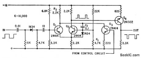
One-shot mvbr Q1-Q2 triggered by input signal, and Q3 controlled by error-detecting signals at output of static inverter, together determine delay at output of Q4.Complete inverter uses six identical delay circuits together with solid-state servo loops to control output voltages and phase angles despite unbalanced loads.-T. J. Gilliam, Three-Phase Inverter with Feedback Loops, Electronics, 35:12, p 48-5l. (View)
View full Circuit Diagram | Comments | Reading(661)
PLL_RTTY_TERMINAL
Published:2009/7/15 1:41:00 Author:Jessie

Uses 741 opamp as limiter, followed by NE565 phase-locked loop, another opamp U3 operating as voltage comparator or slicer, and keying transistor. Terminal requires no filters because incoming signal locks onto VCO whose frequency is placed between those of mark and space tones. As these tones alternate, output of PLL is made to pro-duce plus and minus voltages by connecting voltage comparator to output of NE565. Resulting plus voltage corresponds to mark tone and minus voltage to space tone for use in keying loop circuit of teleprinter. R1 is only adjustment required; article covers adjustment for receiver in SSB mode and in CW mode.-N. Stinnette, Phase-Locked Loop RTTY Terminal Unit, Ham Radio, Feb. 1975, p 36-37. (View)
View full Circuit Diagram | Comments | Reading(2436)
LINE_VOLTAGE_MONITOR
Published:2009/7/15 1:39:00 Author:Jessie
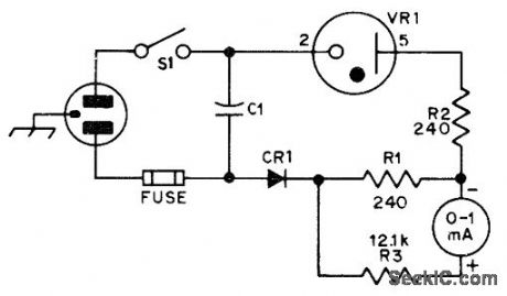
OC3 (VR-105) voltage-regulator tube provides voltage offset that permits greater sensitivity in voltage range of interest Meter scale covers 20-V range centered on about 115VAC,Accuracyismuch better than with AC range of ordinary multimeter,CE1 is 500-PlV 1-A silicon diode.-N Johnson, An AC Line Monitor, QST, Jan,1976, p 27. (View)
View full Circuit Diagram | Comments | Reading(0)
9600_CPS_AT_15_KW
Published:2009/7/15 1:37:00 Author:Jessie
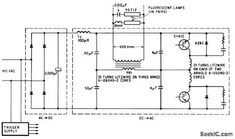
Scr inverter fluorescent lamps in parallel at 9,600 cps with power supply efficiency above 95%. Inverter operates safely without load during interval between turn. on and ionization. RC networks across diodes damp out ringing.-N. Mapham, SCR's Break the Frequency Barrier, Electronics, 38:18, p 88-97. (View)
View full Circuit Diagram | Comments | Reading(1423)
APPLIANCE_TIMER
Published:2009/7/14 19:37:00 Author:May
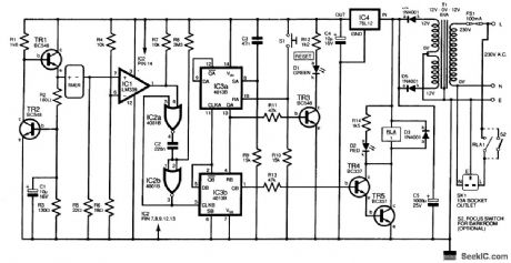
This design uses a low-cost digital kitchen timer to control appliances. No modification to the timer is needed; the only requirement is that it must beep both when the Start button is pressed crud when the period has expired. This appliance timer detects the supply current flowing through the timer, and drives an external relay circuit, which operates loads for a period set by the kitchen timer. A low-voltage supply is formed by transistors TR1 and TR2, a ring-of-2 constant-current source adapted to pro-vide about 1.5 V at the TR1 emitter (e). This powers the timer. At power on, capacitor C3 provides a positive pulse, which sets IC3a (pin 8), one-half of a dual D-type flip-flop. Output QA (pin 13) goes high, which resets IC3b, so that QB (pin1) is low. Transistors TR4 and TR5 are off,and so the relay RLA does not operate However, transistor TR3 is driven on and illuminates the green LED D1 to indicate reset The digital timer can now be set to the desired duration Then switch S1 is pressed which resets IC3a;QA goes low, which enables IC3b When the timer’s Start button is pressed,the Increase in its supply current caused by the beep rises from a few microamperes to 5 mA or more The voltage across resistor R5 rises,and comparator IC1,whose threshold is set by resistors R4 and R5 will output a brief positive pulse This is cleaned up by the monostable formed from IC2a and IC2b,and clocks IC3b Output QB(pin 1) now goes high and powers the relay via the Darlington transistor pair At the end of the period,the first beep clocks IC3b again Output QB(pin 2) goes high to clock IC3a(pin 11);QA goes high and resets IC3b so that the relay switches out. (View)
View full Circuit Diagram | Comments | Reading(0)
AC_DC_CONVERTER
Published:2009/7/15 1:37:00 Author:Jessie

Used for measuring AC voltage with digital DC voltmeter, Besulting signal is equal to average RMS value of applied input signal. When 1-V peak 60-Hz is applied to converter, output should be +0.707 VDC. Connect pin 4 of LM324 to +5 V and pin 11 to -5 V.–S. Ciarcia, Add More zing to the Cocktail, BYTE, Jan 1978,p37-39, 44, 46, 48, 50-52, and 54. (View)
View full Circuit Diagram | Comments | Reading(4528)
EXPANDED_RANGE_AC_VM
Published:2009/7/15 1:36:00 Author:Jessie
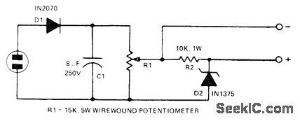
Line voltage is applied to D1, and resulting DC is filtered by C1 R1 delivers equivalent of RMS voltage to 100-V zener D2 through R2 Voltage is developed across R2 Only when voltage applied by R1 exceeds 100 V, for reading with 1000-ohm-per voltmeter To calibrate, rneasure AC line voltage with accurate AC Voltmeter, then adjust R1 so meter across R2 reads 100 V less than this value-W. P. Turner, Expanded Range Line Voltage Meter, 73 Magazine.March 1974, p 54. (View)
View full Circuit Diagram | Comments | Reading(755)
TWINKLE_TREE
Published:2009/7/14 12:29:00 Author:May

Twinkle Tree is an easy project for beginners to build, and its basic circuit has a number of useful applications. The circuit’s visible action appears as a string of 10 LEDs (light-emitting diodes) flashing on, one at a tiine, in sequence, this being repeated so long as the circuit is powered. The LEDs can be used on a small table decoration, in the form of a Christmas tree, or around a picture frame; or they can be placed at various points on a hanging decoration, such as a bunch of mistletoe, or can be incorporated in other decorations or modes. The LED light display provides an interesting and novel twinkling effect. (View)
View full Circuit Diagram | Comments | Reading(1172)
250_W_50_KC_INVERTER
Published:2009/7/15 1:35:00 Author:Jessie

Silicon power transistors in high-speed inverter circuit give con version efficiency up to 90% in changing 28 v d-c to 50 kc at primary of output transformer.-H. T. Breece, Boosting D-C Voltage With Sillcon Transistors, Electronics, 37:29, p 56-66 (View)
View full Circuit Diagram | Comments | Reading(707)
TIMED_NIGHT_LIGHT
Published:2009/7/14 12:27:00 Author:May

A small lamp is turned on via switch Q2 for a predetermined time. S1 initiates the 555 timer cycle, holding on Q1 and switch Q3, supplying power to the circuit, and Q2, turning on the lamp. At the end of the cycle, power is removed from the circuit because Q3 is cut off. Therefore, no current is drawn from the battery during standby. (View)
View full Circuit Diagram | Comments | Reading(881)
FET_MILLIVOLTMETER
Published:2009/7/15 1:34:00 Author:Jessie
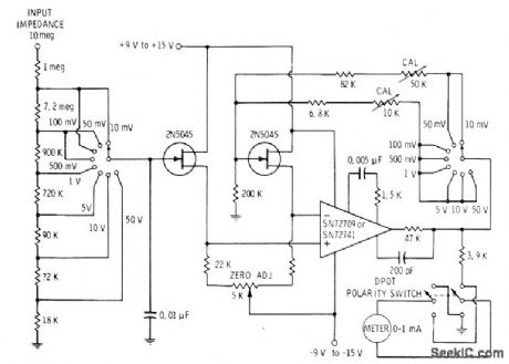
Eight-range meter uses pair of JFETs in bridge arlangement driving meter through opamp, FETs should be reasonably well matched,even though their operation can be balanced with 5K zero-adjust pot.-E. M. Noll, FET Principles, Experiments, and Proiects, Howard W. Sams, Indianapolis, IN, 2nd Ed,, 1975, p zn2-213. (View)
View full Circuit Diagram | Comments | Reading(1667)
ELECTROMETER
Published:2009/7/15 1:33:00 Author:Jessie
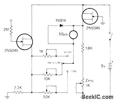
Can be used for picoampere leakage measurements and nonloading voltage measurements. Bridge circuit has three pots for three ranges of sensitivity. Adjust for 0.5, 1.5, and 5 V full scale with appropriate input voltages. With 1000-megohm resistance between point 5 and probe tip, picoammeter gives full-scale deflection on 500 pA. For nonloading voltmeter, apply unknown voltage across same l000-megohm resistor; now 0.5 V will give fullscale reading.-I. Math, Math's Notes, CQ, Oct. 1974, p 26--27. (View)
View full Circuit Diagram | Comments | Reading(4160)
INCANDESCENT_LAMP_LIFE_EXTENDER
Published:2009/7/14 12:26:00 Author:May

The cold resistance of an incandescent lamp is normally very low compared to its operating resistance. Each time such a lamp is turned on, the initial current is several times greater than its rated operating current. The life-extender circuit will work with any incandescent lamp that operates at a voltage of 1.5 to 12 V and a current of 1 A or less. Look up the lamp's normal operating current and, using an ammeter, set R1 so that the normal operating current flows to the lamp. Now, each time the lamp is switched on, the initial current will be limited to its preset value. (View)
View full Circuit Diagram | Comments | Reading(919)
POSITIVE_PEAK_DETECTOR
Published:2009/7/15 1:32:00 Author:Jessie
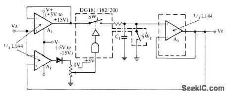
Combination of sillconix triple L144 opamp and DG181 analog switch eliminates errors of conventional diode circuits.Third opamp acts as comparator providing logic drive for operating SW1. Action of circuit is such that most positive analog input is stored. SW2, serves as reset switch.- Analog Switches and Their Applications, Siliconix, Santa Clara, CA, 1976, p 4-9. (View)
View full Circuit Diagram | Comments | Reading(0)
CHRISTMAS_LIGHT_DIMMER
Published:2009/7/14 12:25:00 Author:May
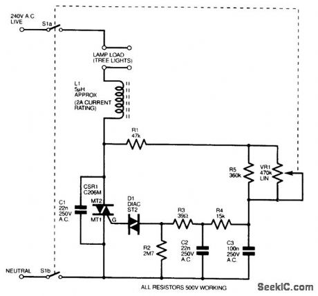
This is based on a standard diac/triac dimmer configuration, which has been optimized for this application. Resistor R2 is, however, optional and was included only to help discharge the capacitors quickly. All capacitors are 260-Vac X2 rated (this is very importctnt), all resistors are 500-V working voltage, and triac CSR1 was chosen for its low holding current so that it would function with small loads. Note that VR1 is fitted with a double-pole mains switch for complete isolation. Even with only one 20-lamp string plugged in (22 W), control is very smooth with barely any trace of hysteresis. This circuit can be built safely on a piece of matrix board, wired point-to-point, provided it is mounted in a completely insulated plastic case and that no external components (i.e.,S1 and VR1) are metal.(Do not build this circuit if you do not understand the safety requirements.) (View)
View full Circuit Diagram | Comments | Reading(1031)
INCANDESCENT_LAMP_TOUCH_CONTROL
Published:2009/7/14 12:18:00 Author:May

An IRF511 power MOSFET controls an incandescent lamp. This circuit is useful where low-voltage dc is used. (View)
View full Circuit Diagram | Comments | Reading(681)
R_Y_TEST_GENERATOR
Published:2009/7/15 0:41:00 Author:Jessie

Uses ICs rather than PROM for automatic generation of sequence of 64 alternating Rs and Ys, plus Baudot codes for carriage return and line feed, as used for testing radioteletype equipment. Circuit in dashed lines generates codes for printing R and Y continuously without regard for line length. Jumper J1 gives choice of normal or inverted output data for keying transmitter with either mark-high or space-high signal. Operates at slightly less than 60 WPM Adjust R1 so clock pulse generator U1 runs at 45.45 Hz Article covers construction and operation-J,Loughmiller ,RTTY Test Generator,Ham Radio.Jan 1978,p 64-66. (View)
View full Circuit Diagram | Comments | Reading(640)
DC_LAMP_DIMMER
Published:2009/7/14 12:16:00 Author:May

The dc lamp dimmer circuit will adjust the brightness of a dc lamp or the speed of a suitable dc motor. An oscillator is formed around Schmitt inverter IC1a, and is buffered by IC1b. This, in turn, drives TR1, which is a Darlington power transistor. The lamp LP1 forms the collector (c) load for the transistor, and this is driven at a nominal 330 Hz. The duty cycle is, however, fully variable using potentiometer VR1. Consequently, the power delivered to the load can be controlled between 5 and 95 percent, approximately. No flicker will be apparent at this frequency. The circuit consumes little power itself and is ideal for controlling car instrument panel lights. (View)
View full Circuit Diagram | Comments | Reading(2808)
300_AND_1800_BAUD_FSK_DEMODULATOR
Published:2009/7/15 0:30:00 Author:Jessie

Uses Exar XR-215 PLL IC having frequency range of 0.5 Hz to 35 MHz. When input frequency is shifted by data bit, DC voltage between pins 2 and 3 reverses polarity. Opamp section is connected as comparator for converting DC level shift to binary output pulse. C1 serves as PLL filter. C2 and C3 are postdetection filters. Table gives typical values of components for two transmission speeds.- Phase-Locked Loop Data Book, Exar Integrated Systems, Sunnyvale, CA. 1978. p 21-28. (View)
View full Circuit Diagram | Comments | Reading(753)
| Pages:610/2234 At 20601602603604605606607608609610611612613614615616617618619620Under 20 |
Circuit Categories
power supply circuit
Amplifier Circuit
Basic Circuit
LED and Light Circuit
Sensor Circuit
Signal Processing
Electrical Equipment Circuit
Control Circuit
Remote Control Circuit
A/D-D/A Converter Circuit
Audio Circuit
Measuring and Test Circuit
Communication Circuit
Computer-Related Circuit
555 Circuit
Automotive Circuit
Repairing Circuit