Basic Circuit
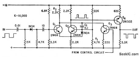
400_CPS_THREE_PHASE_INVERTER_DELAY_CIR_CUIT
Published:2009/7/15 1:42:00 Author:Jessie | From:SeekIC

One-shot mvbr Q1-Q2 triggered by input signal, and Q3 controlled by error-detecting signals at output of static inverter, together determine delay at output of Q4.Complete inverter uses six identical delay circuits together with solid-state servo loops to control output voltages and phase angles despite unbalanced loads.-T. J. Gilliam, Three-Phase Inverter with Feedback Loops, Electronics, 35:12, p 48-5l.
Reprinted Url Of This Article:
http://www.seekic.com/circuit_diagram/Basic_Circuit/400_CPS_THREE_PHASE_INVERTER_DELAY_CIR_CUIT.html
Print this Page | Comments | Reading(3)

Article Categories
power supply circuit
Amplifier Circuit
Basic Circuit
LED and Light Circuit
Sensor Circuit
Signal Processing
Electrical Equipment Circuit
Control Circuit
Remote Control Circuit
A/D-D/A Converter Circuit
Audio Circuit
Measuring and Test Circuit
Communication Circuit
Computer-Related Circuit
555 Circuit
Automotive Circuit
Repairing Circuit
Code: