
Circuit Diagram
Index 613
50_350_MICROSEC_PHANTASTRON_DELAY
Published:2009/7/15 3:23:00 Author:Jessie

Gives 0.5% accuracy. Phantastron furnishes own gate and does not require amplifier to trigger blocking oscillator al output.-NBS, Handbook Preferred Circuits Navy Aeronautical Electronic Equipment, Vol. 1, Electron Tube Circuits, 1963, pN9-2. (View)
View full Circuit Diagram | Comments | Reading(714)
IR_REMOTE_CONTROL_TRIAC_INTERFACE
Published:2009/7/14 10:59:00 Author:May

This circuit can be used to interface a triac to the IR remote control ac loads. (View)
View full Circuit Diagram | Comments | Reading(690)
PUSHBUTTON_TO_DIAL_CONVERTER
Published:2009/7/14 8:38:00 Author:May

Combination of Motorola MC14419 keypad-to-binary converter and MC14408 BCD-to-dial telephone pulse convener is used with 10-switch push-button array to provide correct chain of pulses for dialing number on conventional dial-telephone system. Eleventh SPDT button is used for redial feature; if line called is busy, one press of redial button dials number over again. Number is stored for repeated use until new number is dialed. Check local telephone company regulations before making connections to telephone lines.-I. Math, A Push-Button to Dial Tele-phone Converter, CQ, Sept. 1976, p 36-37.
(View)
View full Circuit Diagram | Comments | Reading(1259)
BUSY_SIGNAL_GEN_ERATOR
Published:2009/7/14 8:36:00 Author:May
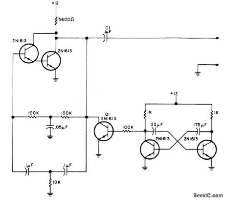
Conventional Bell System busy signal is provided by turning twin-T oscillator at left on and off with low-frequency asymmetrical square wave generated by transistor pair at right. Q1 acts as switch for turning oscillator on and off. Developed for use at repeater in home when autopatch connects to family telephone, to inhibit use of autopatch by mobile station when phone is in use. Article also covers connections to phone line and to repeater.-T. Yocom, An Autopatch Busy Signal, 73 Magazine, Holiday issue 1976, p 148 and 150. (View)
View full Circuit Diagram | Comments | Reading(833)
WAVEFORM_PEAKS_AND_TROUGHS
Published:2009/7/15 2:56:00 Author:Jessie
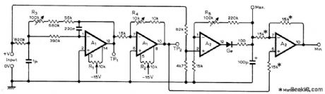
Used in data-logging systems to measure, limits of waveform superimposed on DC level. Requires two LM747CN (dual 741) ICs. Measurements are made with conventional DC voltmeter. Input signal is fed to precision peak detector A1. Same signal goes through active low-pass filter and inversion amplifier whose output at TP2 is the mean value. Differential amplifier A2 subtracts maximum from mean to give minimum value of input. For setup, short input and adjust R1 for 0 V at TP1, adjust R2 for 0 V at TP2, then apply +5 V to input and adjust R3 for+5 V at TP, adjust R4 for-5 V at TP2, and adjust R5 for +5V at Max. output terminal. –K. R. Brooks, Peak and Trough Detector, Wireless World, Feb. 1977, P 45. (View)
View full Circuit Diagram | Comments | Reading(2392)
TOUCH_TONE_BAND_REJECT_FILTER
Published:2009/7/14 8:34:00 Author:May

Cascaded notch filters with active limiter at output provide 20-dB attenuation of either low (697-941 Hz) or high (1209-1633 Hz) groups of tones, as aid to decoding for repeater control functions. All coils are 88-mH toroid. RA is between 5600 and 22,000 ohms, and RB is 1000 to 3000 ohms. Article gives tuning procedure for selecting resistor values and adjusting toroids so each stage rejects different tone in its band.-B. Bretz, Multi-Function FM Repeater Decoder, Ham Radio, Jan. 1973, p 24-32. (View)
View full Circuit Diagram | Comments | Reading(1276)
AUTOPATCH_RELEASE
Published:2009/7/14 8:32:00 Author:May

Control circuit automatically releases telephone autopatch at receiver when called party hangs up, by generating disconnect signal for patch control logic. Action is based on reversal of polarity of phone line when called party answers, and return of polarity to preanswered condition when called party hangs up. Article describes circuit operation and use.-T. R. Yocom, Automatic Auto-patch Release, 73 Magazine, April 1977, p 52. (View)
View full Circuit Diagram | Comments | Reading(1909)
INFRARED_DATA_TRANSMITTER
Published:2009/7/14 8:27:00 Author:May

This figure shows anIrDA transmitter. (View)
View full Circuit Diagram | Comments | Reading(1847)
PHOTOTRANSISTOR_IR_RECEIVER
Published:2009/7/14 8:26:00 Author:May
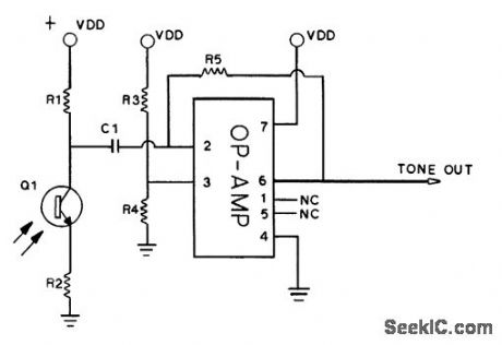
This receiver uses an op amp and a phototransistor as a recetver for IR signals. Q1 is a phototransistor. The op amp is CMOS or FET, such as a TL081, etc. R1 and R2 depend on phototransistor, but are typically 2.2 kΩ and 330Ω, respectively. R3=R4=10 kΩ, R5=100 kΩ, and C1 is 0.1 μF (or larger ). (View)
View full Circuit Diagram | Comments | Reading(2581)
TOUCH_TONE_DRIVE_FOR_LOUDSPEAKER
Published:2009/7/14 8:25:00 Author:May

Encoder is held In front of microphone to access and use autopatch of repeater, Acoustic coupling eliminates need for opening new transceiver to make wire connections, which would void guarantee Uses Motorola MC14410P IC with KB1 keyboard (Polypaks 92CU3149). Q1 and Q2 are 2N3643 or equivalent Y1 IS 1,000 MHz crystal (Mariann Labs ML18P or Sherold Crystal HC-6) Transistors Q1 and Q2 boost out-put enough to drive 8-ohm loudspeaker Total current drain is 35 mA idling and 100 mA with full drive.-C. Gorski, A Low-Cost Touch-Tone Encoder, QST, Oct 1976, p 36-37. (View)
View full Circuit Diagram | Comments | Reading(775)
IR_REMOTE_CONTROL_RELAY_INTERFACE
Published:2009/7/14 8:23:00 Author:May

This circuit can be used to interface a relay to the IR remote control in order to control large ac or dc loads. (View)
View full Circuit Diagram | Comments | Reading(750)
IR_REMOTE_CONTROL_TEST_SET
Published:2009/7/14 8:22:00 Author:May
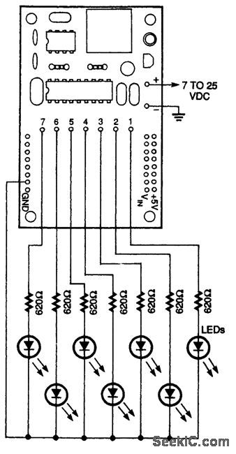
This circuit can be used to check out operation ofthe IR remote control. (View)
View full Circuit Diagram | Comments | Reading(797)
500_MC_TO_4000_MC_1_STEP_MULTIPLIER
Published:2009/7/15 2:56:00 Author:Jessie
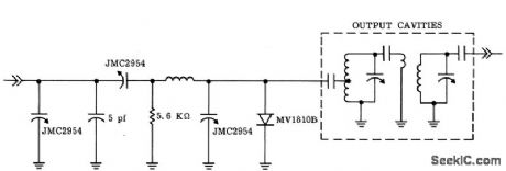
Combines both lumped and coaxial cavity techniques with varctctor to serve as octupler. Coupling from varctctor to first cavity must be exceedingly tight.-G. Schaffner, Varactor Multipliers Provide High Output-Power Above 6 GHz, Motorola Application Note AN.213, Dec. 1965. (View)
View full Circuit Diagram | Comments | Reading(683)
SSTV_DEFLECTION_DRIVE
Published:2009/7/15 2:55:00 Author:Jessie

Developed for use in line time-base amplifier of 4-Hz slow-scan TV system. Emitter-follower in driver stage is used with first transistor to match output impedance of UJT sawtooth oscillator. Will drive deflection coils of 17-ineh CRT (coil resistance about 5 ohms).-M. Hadley, Deflection Coil Driver for Slow-Scan Television, Wireless World, March 1974, p. 18. (View)
View full Circuit Diagram | Comments | Reading(3019)
IR_REMOTE_CONTROL_DC_INTERFACE
Published:2009/7/14 8:21:00 Author:May

This circuit can be used to interface dc loads up to 500 mA to the IR remote control. (View)
View full Circuit Diagram | Comments | Reading(530)
TOUCH_TONE_ENCODER
Published:2009/7/14 8:19:00 Author:May

Uses 555 timers to generate Touch-Tone frequencies in pairs using two of seven possible frequencies, under control of standard 12-button pad. Adjust R10 so low-group oscillator reads 941 Hz at pin 3 of U1 when * key is pressed. Frequencies of 852, 770, and 697 Hz will then be correct within 2 % when 7, 4, and : are pressed, if 1 % resistors are used and 0.047-ptF capacitors are tantalum or Mylar, Automatic push-to-talk control uses U4 connected as 1-s mono MVBR driving relay K1.-H. M. Berlin, Homebrew Touch-Tone Encoder, Ham Radio, Aug. 1977, p 41-43. (View)
View full Circuit Diagram | Comments | Reading(787)
TRIPLER_WITH_OVERLAY_TRANSISTOR_GIVES_102_GC
Published:2009/7/15 2:55:00 Author:Jessie
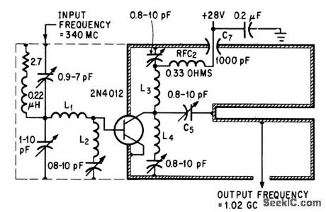
Single overlay transistor eliminates conventional transistor amplifier and chain of varactor frequency multipliers. Output power is 3.5 w.-H. C. Lee and G. J. Gilbert, Overlay Transistors Move into Microwave Region, Electronics, 39:6, p 93-95. (View)
View full Circuit Diagram | Comments | Reading(759)
200_MC_TO_600_MC_HARMONIC_TRIPLER
Published:2009/7/15 2:55:00 Author:Jessie
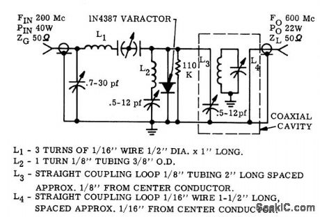
Uses single varactor to give 20 w output from 40 w input.-G. Schaffner and J. Cochran, Varactor Diodes and Circuits for High Power Output and Linear Response, Motorola Application Note AN-191, Aug. 1965. (View)
View full Circuit Diagram | Comments | Reading(680)
50_W_TWO_STAGE_OUTPUT
Published:2009/7/15 2:54:00 Author:Jessie
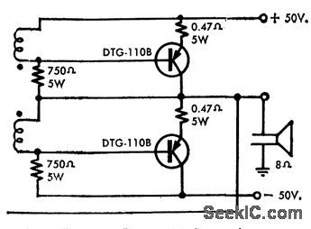
Produces over 50-w rms audio power and has simple drive requirements.-High-Power Nu-Base Germanium Transistors (Delco Radio ad), Electronics, 39:7, p 20-21. (View)
View full Circuit Diagram | Comments | Reading(1344)
AF_PHASE_SHIFTER
Published:2009/7/15 2:54:00 Author:Jessie

Developed for testing chroma demodulator in color TV receiver. Audio oscillator is used as source of sine waves. First stage is phase inverter, followed by two emitter-followers. Resulting output signals of opposite phase are combined through a small capacitor (0.022μF, selected for frequency used) from one channel and 50K variable resistor from other channel. 90°phases are judged by position of sine waves on screen of CRO; 90° is halfway between 0° and 180°.-C. Babcoke, Waveforms Explain Chroma Demodulators, Electronic Servicing, Sept. 1972, p 22-23, 26-28, and 30. (View)
View full Circuit Diagram | Comments | Reading(968)
| Pages:613/2234 At 20601602603604605606607608609610611612613614615616617618619620Under 20 |
Circuit Categories
power supply circuit
Amplifier Circuit
Basic Circuit
LED and Light Circuit
Sensor Circuit
Signal Processing
Electrical Equipment Circuit
Control Circuit
Remote Control Circuit
A/D-D/A Converter Circuit
Audio Circuit
Measuring and Test Circuit
Communication Circuit
Computer-Related Circuit
555 Circuit
Automotive Circuit
Repairing Circuit