
Circuit Diagram
Index 620
UNITY_GAIN_TEMPERATURE_STABLE_D_C_AMPLIFIER
Published:2009/7/14 5:52:00 Author:May
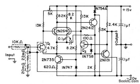
Two bootstrapped cathode followers are combined to form differential input stage, where one gate serves as feedback input and other as signal input. Field effect transistors Q1 and Q2 are matched.-Texas In-struments Inc., Solid-State Communications, McGraw-Hill, N.Y.1966, p139. (View)
View full Circuit Diagram | Comments | Reading(697)
COMPLEMENTARY_PAIR_LOW_LEVEL
Published:2009/7/14 5:50:00 Author:May
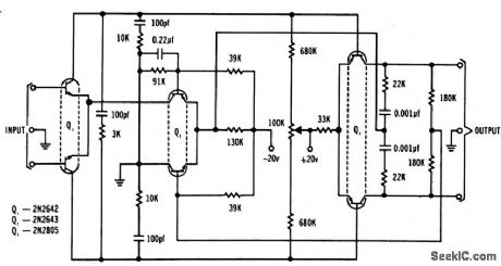
Dual transistors provide extremely high gain, to give greater stability with fewer stages. Circuit has low drift and high common-mode rejection (120 db) for either differential or single-ended outputs. Differential input impedance is 500K minimum, gain-bandwidth product is 5Mc, and low-frequency voltage gain is 68 db.-Texas Instruments Inc Solid-Slate Communications, McGraw-Hill,N.Y.1966, p290. (View)
View full Circuit Diagram | Comments | Reading(721)
FSK_DEMODULATOR_1
Published:2009/7/15 2:19:00 Author:Jessie
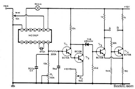
Uses IC originally developed for stereo multiplex decoders, containing phase-locked loop suitable for demodulating teleprinter FSK signals. Circuit shown requires only small input signal for phase lock, gives visual indication with lamp when phase lock has occurred, and requires only pair of 2N3055 drive transistors between outputs A-B and teleprinter receiving solenoids. Article also gives this output circuit and setup procedure.-K S. Beddoe, Teleprinter Terminal Unit Uses Phase-Locked Loop, Wireless World, Dec. 1973, p 605. (View)
View full Circuit Diagram | Comments | Reading(2079)
UNATTENDED_RECORDER
Published:2009/7/14 5:44:00 Author:May

Uses 567 tone decoder in circuit designed to respond to 1-kHz tone, to turn on recorder for taking message when receiver of amateur station is unattended. R6, C5, and 741 opamp U2 form timer that turns on RS-267-20t6 transistor and pulls in relay to turn on tape recorder for recording about 30-s message. Relay then drops out. Use well-regulated 5-V supply. All transmitters using this ser vice must have 1-kHz audio encoders for proclueing required control frequency Article givesconstruction and adjustment details.-R Perlman ,The FM. Auto-StarT. 73 Magazine, April 1974.p 21 and 23-24. (View)
View full Circuit Diagram | Comments | Reading(653)
PLL_FOR_RTTY
Published:2009/7/15 2:17:00 Author:Jessie

Complete phase-locked loop uses all four sections of LM3900 quad linear opamp. Variable capacitor is set to give center frequency of 2.2 kHz for VCO. Once in lock, loop will maintain lock over range of 1.55 to 2.9 kHz, to cover tones normally used in RTTY. Additional keying circuit for TTY selector magnets and more filtering of output completes setup for driving printer, C1 is 2N706, with 33K resistor in base circuit.-C. Sondgeroth, More PLL Magic, 73 Magazine, Aug. 1976, p 56-59. (View)
View full Circuit Diagram | Comments | Reading(851)
CONSTANT_CURRENT_DIODE_AS_COLLECTOR_LOAD
Published:2009/7/14 5:41:00 Author:May

Current-limited Currector diode isolates transistor amplifier output from changes in supply volatge and serves also as collector load impedance. Gain is over 60 db at 50 to 100kc.-N. Welsh. How Diodes Keep Current to Constant Value. Electronics.36:4,p74-78 (View)
View full Circuit Diagram | Comments | Reading(0)
CURRENT_REGULATOR_FOR_0_100_MA
Published:2009/7/14 5:40:00 Author:May

Constant. current Currector diode and shunting zener diode together maintain constant current over extremes of input voltage for both normal and shorted loads.-N. Wejsh, How Diodes Keep Current to Constant Value, Electronics, 36:4, p 74-78. (View)
View full Circuit Diagram | Comments | Reading(665)
STEREO_TAPE_PLAYBACK
Published:2009/7/14 5:39:00 Author:May

Single Sprague ULN-2126A IC provides preamplification for two channels along with 2-W output power for driving stereo power amplifier. Values shown give equalization required for tape playback. Single ganged tone control serves for both treble and bass adjustment-E. M. Noll, Linear IC Principles, Experiments, and Projects, Howard W. Sams, Indianapolis, IN, 1974, p 237 and 243. (View)
View full Circuit Diagram | Comments | Reading(1005)
RAM_FOR_RTTY
Published:2009/7/15 2:14:00 Author:Jessie
Erasable MC2102 1024-bit RAM stores two Teletype lines (128 characters) of Baudot code for readout at machine speed Can also serve in place of tape loop for frequently used code messages such as CQ calls. Values shown with IC1 timer are for 728-Hz master clock (16× 45.45 bauds). Stored message is volatile, disappearing when power is turned off. For permanent storage, use ROM in place of RAM.-H. P. Fischer, RTTY Scratchpad Memory, 73 Magazine, June 1977, p 54-55. (View)
View full Circuit Diagram | Comments | Reading(1718)
CLASS_AB_PUSH_PULL_AUDIO
Published:2009/7/15 2:14:00 Author:Jessie
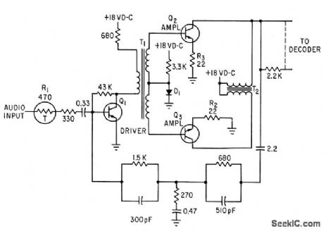
Sensistor R1 in a-c coupled driver compensates for effects of temperature on amplifier gain on amplifier gain. Negative feedback stabilizesfrequency and phase response. Circuit drives 20 decoders in Mercury spacecraftcommand receiver.-R. Elliott, First Details on Mercury Spacecraft Command Receiver,Electronics, 36;5, p 32-35. (View)
View full Circuit Diagram | Comments | Reading(846)
THREE_PHASE_REGULATOR
Published:2009/7/15 2:13:00 Author:Jessie

When used with three-phase static inverter employing scr's and magnetic amplifiers, provides 25.millisec recovery time when load is switched from 2.5 amp to 0. The three bridges use one zener diode in common as non-linear element. Silicon transistor amplifies unbalance in each bridge.-M. Lilienstein, Static Inverter Delivers Regulated 3-Phase Power, Electronics, 33:28, p 55-59. (View)
View full Circuit Diagram | Comments | Reading(1807)
TONE_CONTROL
Published:2009/7/15 2:12:00 Author:Jessie

Unlike bipolar transistor, fet maintains full dynamic range whileloading R.C tone control network.-FET's and RC Networks (Siliconix ad), Electronics,39:4, p 71. (View)
View full Circuit Diagram | Comments | Reading(1888)
5_V_SWITCHING_1
Published:2009/7/14 4:41:00 Author:May

Darlington pair Q1-Q2 serves as switch for regulator using Signetics 550 as threshold detector. Design equations are given. Exact frequency of self-oscillating switching regulator depends primarily on parasitic components. If frequency is important, as in applications requiring EMI suppression, regulator may be locked to external square-wave drive signal fed to reference terminal.- Signetics Analog Data Manual, Signetics, Sunnyvale, CA, 1977, p 661-662. (View)
View full Circuit Diagram | Comments | Reading(796)
WIDE_RANGE_VOLTAGE_PROBE
Published:2009/7/15 2:11:00 Author:Jessie

Indicates presence of AC or DC voltages from 3 to 350 V with no ranges witching, using LED as indicator. Transistors serve essentially as constant-current supply for LED Voltage capability can be increased to 450 V by adding suitable base-emitter resistor Rbe; typical value is 60 ohms, which somewhat impairs low-voltage operation.-G. Jones, Voltage Probe, Wireless World, Aug. 1976, p 52.
(View)
View full Circuit Diagram | Comments | Reading(1106)
COAX_DRIVER_AND_RECEIVER
Published:2009/7/14 4:41:00 Author:May
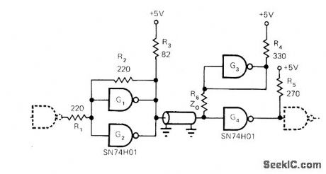
Uses two TTL gates of SN74H01 package to form either driver or receiver for transmitting data over RG59 or RG174 coax at rates exceeding 10 megabits per second, with distance increasing from 400 meters at 10 Mb/s to over 1000 meters at 100 kb/s for RG59 and lesser distances for RG174. Can also be used for twisted-pair lines but at lower data rates. Bias gate G3 exhibits low output impedance, for terminating channel load resistor R6.-R. W. Stewart, Two TTL Gates Drive Very Long Coax Lines, EDN Magazine, Oct, 1, 1972,p49. (View)
View full Circuit Diagram | Comments | Reading(1030)
AFSK_TONES
Published:2009/7/15 2:11:00 Author:Jessie
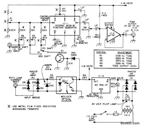
Generates tones needed for either 170- or 850-Hz frequency shift in automatic frequency-shift keying of B'FEY equipment. Independent adjustments are provided for each tone, Sine-wave output has constant amplitude, with excellent tone frequency stability. Circuit permits plug-in operation in any RTTY loop, independent of loop polarity or grounding. Article covers construction and adjustment.-J. C. Roos, Universal AFSK Generator, 73 Magazine, July 1974, p 37-40, 42, and 44-46.
(View)
View full Circuit Diagram | Comments | Reading(1991)
MULTISTAGE_PROGRAMMABLE_AMPLIFIER
Published:2009/7/14 4:42:00 Author:May
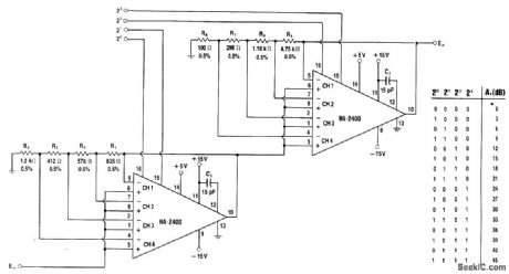
Cascading of two HA-2400 four-channel programmable amplifiers gives choice of 16 different values of gain, ranging from 0 to 45 dB, by applying logic pulses to control inputs for pins 15 and 16 in accordance with truth table shown.-W. G. Jung, IC Op-Amp Cookbook, Howard W. Sams, Indianapolis, IN, 1974, p 433-435. (View)
View full Circuit Diagram | Comments | Reading(818)
5OO_MICROAMP_AT_3O_TO_30000_CPS
Published:2009/7/14 4:43:00 Author:May


Used to drive 60-mh transducer at constant current without allowing d-c through transducer. Achieved by biasing Q3 and Q4 on all the time, so each acts as collector resistance for the other.-S. Sokol, Transistor Pair Provides Constant-Current Drive, Electronics, 35:38, p 56. (View)
View full Circuit Diagram | Comments | Reading(583)
MOS_FET_AMPLIFIER
Published:2009/7/15 2:10:00 Author:Jessie

Circuit draws only 6 microamp while providing voltage gain over200.-G. G. Luettgenau and S.H. Barnes, Designing With Low-Noise MOS FETs: A LittleDifferent But No Harder, Electronics, 37:31, p 53-58. (View)
View full Circuit Diagram | Comments | Reading(886)
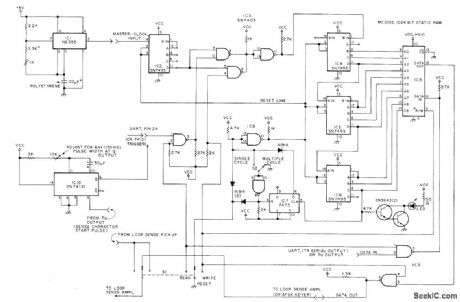
START_UP_CONTROL
Published:2009/7/14 4:43:00 Author:May

Simple, smooth start-up circuit for phase-locked oscillator maintains synchronism with AC line despite presence of large transients, and maintains phase-angle limits as required for controlling firing angle of SCR. Article describes how two separate loops are used in circuit to achieve required locking with line. Values of R6, R7, R8, C5, and C6 are chosen to meet system response time, Other unmarked values depend on operating factors; for 60-Hz line and 6X frequency multiplication by VCO, typical values are R1 39K, R2, 27K, R3 47K, C1 0.1μF, and C2 0.22μF.-J. C. Hanisko, Five IC's Make Ainsworth Oscillator with Start-Up Control, EDN Magazine, March 5, 1977, p 113 and 115. (View)
View full Circuit Diagram | Comments | Reading(889)
| Pages:620/2234 At 20601602603604605606607608609610611612613614615616617618619620Under 20 |
Circuit Categories
power supply circuit
Amplifier Circuit
Basic Circuit
LED and Light Circuit
Sensor Circuit
Signal Processing
Electrical Equipment Circuit
Control Circuit
Remote Control Circuit
A/D-D/A Converter Circuit
Audio Circuit
Measuring and Test Circuit
Communication Circuit
Computer-Related Circuit
555 Circuit
Automotive Circuit
Repairing Circuit