
Circuit Diagram
Index 616
SEQUENCE_GENERATOR
Published:2009/7/15 2:44:00 Author:Jessie

Uses gated shift register assembled from 7475 D-type latch, along with four EXCLUSIVE-OR gates. Clock pulse should be narrow to avoid race-around effects.-P. D, Maddison, Sequence Generator, Wireless World, Dec. 1977, p 80. (View)
View full Circuit Diagram | Comments | Reading(1364)
12_V_PLAYBACK_PREAMP
Published:2009/7/14 7:56:00 Author:May

Provides standard NAB equalization Gain is decreased gradually from 60 dB at 20 Hz to 32 dB at 20 kHz in accordance with NAB playback curve Playback head is represented by 3.3K resistor.- Audio Hand-book, National Semiconductor, Santa Clara, CA, 1977, p 2-31-2-37.
(View)
View full Circuit Diagram | Comments | Reading(806)
FSK_GENERATOR_FOR_CASSETTE_DATA
Published:2009/7/14 7:54:00 Author:May

Uses two 565 PLL ICs, locked to 800-Hz system clock but oscillating at 6.4 kHz and 4.8 kHz, to provide FSK signals for recording digital data on ordinary cassette tape. Harmonic suppression of square-wave output is taken care of automatically by high-frequency roll off characteristic of tape recorder. Incoming data determines which oscillator feeds its signal to recorder.- Signetics Analog Data Manual, Signetics, Sunnyvale, CA, 1977, p 859-860.
(View)
View full Circuit Diagram | Comments | Reading(964)
COMPLETE_40_MC_160_MC_QUADRUPLER
Published:2009/7/15 2:44:00 Author:Jessie
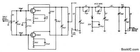
Transistor drive stage provides 10 db gain at 70% efficiency. Output power is 80 mw into 200 ohms. All coils are 1/2 inch diameter, using No.14 wire, unless otherwise specified.-R. C. Wonson, Designing VHF Varactor Multipliers, EEE, 11:12, p 48-52. (View)
View full Circuit Diagram | Comments | Reading(633)
AUTOMATIC_RANGE_EXPANSIO_IV
Published:2009/7/14 7:48:00 Author:May


Instrumentation tape recorder technique folds recorded signal over and reuses same VCO range three times, at three different gains, for increasing dynamic recording range to over 10,000. Two comparators select one of three amplifier gains according to level of input signal and record selected gain on separate control track. During playback, control track signal eCON is used to select corresponding inverse gain for unfolding recorded signal. Level of input signal eIN, in range of 0-10 V, is sensed by comparators whose preset thresholds are determined by pots V1 and V2. If input is less than V1, both comparator outputs are low and section 1 of HA2405 four-channel opamp is selected for recording at 10 times input. If input is greater than V1 and less than V2, section 2 having gain of -2 is selected so direction of eREC is reversed. If eIN is greater than V2, both comparators are high and section 4 is selected for gain of +1/3, so eREC again reverses to cross VCO range for third time. Outputs of comparators are summed to form three-level signal for recording on control track.-J. R. White, Comparator Technique Expands Tape Recorder's Range, EDN Magazine, April 5, 1975, p 111, 113, and 115. (View)
View full Circuit Diagram | Comments | Reading(560)
REDUCING_ODD_HARMONIC_DISTORTION
Published:2009/7/15 2:44:00 Author:Jessie

Grid-plate transfer characteristic of class-B amplifier is linearized to eliminate harsh odd-harmonic distortion, through use of compensation network having nonlinear transfer function. Distortion is cut to 2.6% at 16 w output.-B. Sklar, Reducing Distortion in Class.B Amplifiers, Electronics, 32:21, p 54-56. (View)
View full Circuit Diagram | Comments | Reading(1272)
60_420_CPS_FREQUENCY_SEPTUPLER
Published:2009/7/15 2:43:00 Author:Jessie

Seven saturable-core transformers, with series-star connected multiple primary windings and series-aiding secondaries, serve as static frequency multipliers delivering 40 w at 420 cps. Input may be three-phase (A) or single phase (B).-W. A. Geyger, Frequency Septupler Provides Stable 420-Cps Voltage, Electronics, 36:18, p 58-61., (View)
View full Circuit Diagram | Comments | Reading(736)
1_HR_TIME_DELAY
Published:2009/7/15 2:42:00 Author:Jessie

Achieved by periodically sampling voltage on timing capacitor, using sampling pulse generated by 2-cps ujt relaxation oscillator. Between samples, timing capacitor is isolated from emitter of ujt by low-leakage planar silicon diodes.- Transistor Manual, Seventh Edition, General Electric Co. 1964, p 321. (View)
View full Circuit Diagram | Comments | Reading(651)
CONTROLLED_DURATION__PULSES
Published:2009/7/15 2:42:00 Author:Jessie
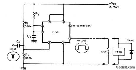
Economical Signetics IC provides output pulse currents up to 200mA at duration ranging from microseconds to many minutes depending on values used for R3 and C2. Input pulses may have duration under a microsecond, negative-going. With positive-going input pulses, output will be delayed until trailing edge occurs, Diode is required across output relay coil to suppress transients that might damage IC and cause automatic retriggering.-J. B. Dance, Simple Pulse Shaper or Relay Driver, Wireless World, Dec. 1973, p 605-606. (View)
View full Circuit Diagram | Comments | Reading(791)
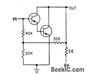
CONSTANT_CURRENT_CONTROL
Published:2009/7/14 5:38:00 Author:May

Uses pnp and npn current sources connected to regulate each other's reference. Values shown are for 1 ma, but R1 and R2 can be changed to give other constant value of current. Applied voltage must be at least 8V.-F. C. Allen, Two-Terminal Constant-Current Device, EEE, 13:10, p 71-72. (View)
View full Circuit Diagram | Comments | Reading(890)
FREQUENCY_MULTIPIJER
Published:2009/7/15 2:42:00 Author:Jessie
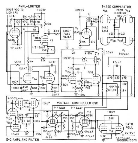
Phase comparator is combined with divider and digital feed. back loop to give highly accurate frequency multiplication over wide band of inputs. Multiplying factor is 1,000, but technique is adaptable to other values. Amplified output of phase comparator is used to regulate voltage-controlled oscillator.-W. O. Brooks, Stepping up Frequency with Counter Circuits, Electronics, 32:29, p 60-62. (View)
View full Circuit Diagram | Comments | Reading(765)
BLOWN_FUSE_INDICATOR
Published:2009/7/14 5:38:00 Author:May

Used with quick-blow fuses in high-power audio amplifier using split power supply, when fuse blows, transistor shunting it is turned on and ρasses current to corresponding indicator lamp, Maximum current in blown-fuse condition is less than 1mA.-I, Flindell, Amplifier Blown-Fuse Indicator, Wireless World,Sept. 1976, p 73. (View)
View full Circuit Diagram | Comments | Reading(1593)
DARLINGTON_WITH_VOLTAGE_DIVIDER
Published:2009/7/15 2:42:00 Author:Jessie
Additional resistors in voltage divider reduce bias voltage, to simplify manufacture as integrated circuit. Useful up to 100 kc.-L.Pollock and R. Gutteridge, Latest Design Techniques for Linear Microcircuits, Electronics, 35:41, p 47-49. (View)
View full Circuit Diagram | Comments | Reading(1096)
DUAL_TIMER
Published:2009/7/14 5:38:00 Author:May

Two are sometimes better than one. This dual timer contains a 556 IC, which contains two 555 timers in one package. (View)
View full Circuit Diagram | Comments | Reading(1046)
PLAYBACK_OF_PULSE_TRAINS
Published:2009/7/14 5:37:00 Author:May

Teledyne Phil-brick 4702 frequency-to-voltage converter Circuit provides ripple filter required for converting recorded square waves in frequency range of 0.5 to 5 kHz to desired analog output in range of 2 to 8 VDC Report covers problems of recording and playing back pulse trains.-“V-F’s, V-F’s, and Audio Tape Recorders,” Teledyne Philbrick, Dedham, MA, 1974, AN-11. (View)
View full Circuit Diagram | Comments | Reading(1515)
OVERLOAD_PROTECTION
Published:2009/7/14 5:37:00 Author:May

Protection circuit detects excessive load current and reduces output voltage proportionately. Values shown limit output current to 530 ma for short-circuit, while holding output voltage at 10 v during normal operation.-C. Yarker, Over. load Protection Circuit Uses low-Power Transistor, Electronics, 35:13, p 60. (View)
View full Circuit Diagram | Comments | Reading(2782)
M_ESSAGE_CONTROLLED_RECORDER
Published:2009/7/14 5:36:00 Author:May

Circuit turns on tape recorder whenever input signal is present in receiver, and turns off recorder when signal goes off. Applications include monitoring local FM repeater for daily usage to obtain call signs of users, or unattended recording of messages left by other amateur stations, Uses cheap cassette tape recorder with autostop, operating at 6 V obtained from 12-V receiver sup-ply by series regulator Q1 and zener D1. Connection to mute or squelch circuit of receiver is shown for set having CA3089E in IF tail end. Darlington pair Q2-Q3 effectively removes base supply for on to turn recorder off. LED comes on when recorder is on. Q1 is NPN power transistor, while Q2 and Q3 are small-signal NPN transistors.-F. Johnson, Automatic Taping Unit, 73 Magazine, May 1977, p 98-99. (View)
View full Circuit Diagram | Comments | Reading(710)
100_W_60_CPS_INVERTER
Published:2009/7/15 2:41:00 Author:Jessie

Permits operation of small a-c appliances from auto or boot storage battery. Frequency changes some what with temperature because sensing-input transistor (2N1302) is germanium.-Texas Instruments Inc, Transistor Circuit Design, McGraw-Hill, N,Y., 1963, p 457. (View)
View full Circuit Diagram | Comments | Reading(723)
45_W_A_F_OUTPUT
Published:2009/7/15 2:40:00 Author:Jessie
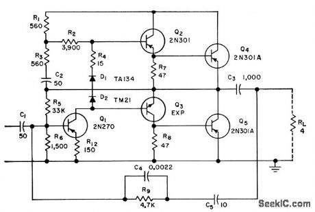
Operates with convection cooling over temperature range of -10 to +50℃. Forward voltage drop of diodes decreases with increasing temperature, to hold emitter currents essentially constant. Uses quasi complementary symmetry.-M. B. Herscher, Designing Transistor A.F Power Amplifiers, Electronics, 31:15, p 96-99. (View)
View full Circuit Diagram | Comments | Reading(2357)
SELF_STARTING_DATA_GENERATOR
Published:2009/7/14 7:14:00 Author:May

Pseudo-random sequence built from shift resisters and exclusive-OR gates often are used to supply binary test data. If constructed from 100-kΩ ECL parts, such generators can run at up to 200 Mbits/s.Although an N-bit shift register can be connected to generate a sequence that repeats every 2N-1 bits,if it should start up in its all-zeros state, no output will be generated. What is needed is a counter to inject a 1 or to preload the shift register whenever N consecutive zeros are detected. The illustratesd circuit generates a 127-bit sequence. It provides a synchronization pulse once per repetition without using additional parts ,and it is guaranted to start. It uses the “wired-OR” property of ECL to generate a 1-bit period negative sync pulse when six zero are present (only five of these zeros are consecutive; a different set of N-1 bits might br needed if a longer shift register is used ). The sync pulse parallel-loads the shift register with the next state in the sequence. As a result, no seven-zero detector is needed to start the generator. (View)
View full Circuit Diagram | Comments | Reading(1931)
| Pages:616/2234 At 20601602603604605606607608609610611612613614615616617618619620Under 20 |
Circuit Categories
power supply circuit
Amplifier Circuit
Basic Circuit
LED and Light Circuit
Sensor Circuit
Signal Processing
Electrical Equipment Circuit
Control Circuit
Remote Control Circuit
A/D-D/A Converter Circuit
Audio Circuit
Measuring and Test Circuit
Communication Circuit
Computer-Related Circuit
555 Circuit
Automotive Circuit
Repairing Circuit