Measuring and Test Circuit
LINE_VOLTAGE_MONITOR
Published:2009/7/9 21:16:00 Author:May | From:SeekIC
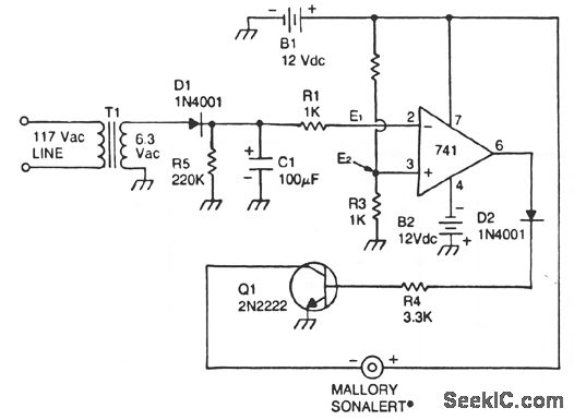
This circuit uses a type 741 op amp as a voltage comparator. One input of the 741 is connected to a reference voltage (a 12-V battery) through a resistor voltage divider. The potential at the noninverting input of the 741 is approximately 3 V. The inverting input of the op amp comparator is connected to the output of a line-operated 8-V power supply. When the ac power main fails, T1 will no longer be energized, so the charge stored in capacitor C1 will begin to discharge through resistor R5. When the capacitor voltage drops below the reference voltage of 3 V, the output of the comparator becomes high. This output condition will forward bias transistor Q1, causing the Sonalert to sound the alarm. The time constant of the R5/C1 combination is 22 seconds-long enough to prevent noise from triggering the alarm.
Reprinted Url Of This Article:
http://www.seekic.com/circuit_diagram/Measuring_and_Test_Circuit/LINE_VOLTAGE_MONITOR.html
Print this Page | Comments | Reading(3)

Article Categories
power supply circuit
Amplifier Circuit
Basic Circuit
LED and Light Circuit
Sensor Circuit
Signal Processing
Electrical Equipment Circuit
Control Circuit
Remote Control Circuit
A/D-D/A Converter Circuit
Audio Circuit
Measuring and Test Circuit
Communication Circuit
Computer-Related Circuit
555 Circuit
Automotive Circuit
Repairing Circuit
Code: