Circuit Diagram
Index 1624
Transfusion warmer 1
Published:2011/6/27 1:42:00 Author:Nicole | Keyword: Transfusion warmer
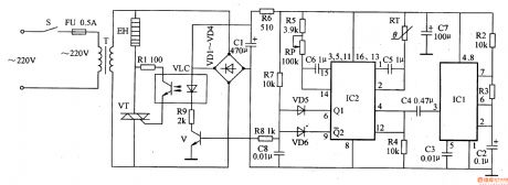
This transfusion warmer circuit is composed of astable multivibrator, temperature detector control circuit, heating circuit and power supply, it is shown in the figure 9-151.
The astable multivibrator is made of resistors R2, R3, capacitors C2, C3 and time base integrated circuit IC1.
The temperature detector control circuit consists of trigger integrated circuit IC2, thermal resistor RT, potentiometer RP, resistors R4, R5, R7-R9, capacitors C4-C6, transistor V and diodes VD5, VD6.
The heating circuit is composed of light clutch VLC, resistor R1, thyristor VT and heater EH.
(View)
View full Circuit Diagram | Comments | Reading(824)
Psychological stress alleviating 3
Published:2011/6/27 2:24:00 Author:Nicole | Keyword: psychological stress, alleviating
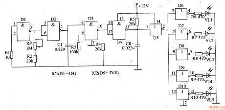
This psychological stress alleviating circuit is composed of low frequency oscillator, high frequency oscillator and not gate circuit, it is shown in the figure 9-150.
The low frequency oscillator is made of not gate integrated circuits D1, D2 and oher peripheral devices, the work frequency is 2-20Hz.
The high frequency oscillator consists of D3, D4 and oher peripheral devices, the work frequency is 1KHz.
The low frequency oscillator's frequency can be changed between 2-20Hz by adjusting potentiometer RP, then the flashing frequency of LEDs will be changed.
(View)
View full Circuit Diagram | Comments | Reading(707)
VHF VFO circuit
Published:2011/7/4 6:56:00 Author:John | Keyword: VHF, VFO

The author has encountered a device which has both drifting and shifting problems. These two kinds of problems both have a high ratio. Although employed in the communications sector at that time, I had not solved the problems for months ( cobbler's shoes syndrome). A closer examination was given to only find that there is some debris below the rotor of main tuning capacitor. Under normal circumstances, the rotor of the capacitance is connected to the chassis through its frame. But a brass or iron triangle of ground or spring clip should be placed around the bearing in front of the rotor because the rotor must rotate.
(View)
View full Circuit Diagram | Comments | Reading(1547)
Psychological stress alleviating 2
Published:2011/6/27 2:16:00 Author:Nicole | Keyword: psychological stress, alleviating
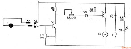
This psychological stress alleviating circuit is composed of power supply circuit, detection circuit and output circuit, it is shown in the figure 9-149.
The power supply circuit is made of power supply switch S, battery GB, current limiting resistor R3 and power supply indication LED VL.
The detection circuit consists of detection electrode A, plug XP, socket XS, potentiometer RP1 and transistor V1.
The output circuit is composed of resistors R1, R2, potentiometer RP2, Zener diode VS, transistor V2 and ammeter PA.
(View)
View full Circuit Diagram | Comments | Reading(439)
Motor brake
Published:2011/7/1 1:38:00 Author:Nicole | Keyword: motor, brake
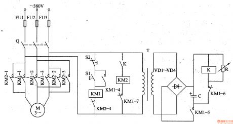
The motor brake circuit is composed of power transformer T, rectifier diode VD1-VM, changeable resistor R, capacitor C, relay K, AC contactor KM1, KM2 and starter button S1, stop button S2, it is shown in the figure 8-65.
After the starter button S1 is pressed, AC contactor KM1 works, the normally open contact KM1-1-KM1-5 is turned on, the normally closed contact KM1-6-KM1-7 is turned off, motor M runs, the power transformer T works too, after the induced voltage is rectified by VD1-VD4, it charges to capacitor C.
(View)
View full Circuit Diagram | Comments | Reading(1222)
Psychological stress alleviating 1
Published:2011/6/27 2:07:00 Author:Nicole | Keyword: psychological stress, alleviating
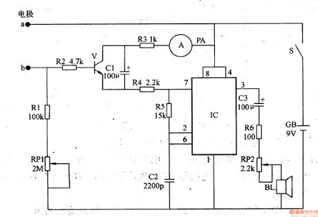
This psychological stress alleviating circuit is composed of skin resistance detection/indication circuit and audio circuit, it is shown in the figure 9-148.
The skin resistance detection/indication circuit is made of electrodes a, b, resistors R1-R4, potentiometer RP1, capacitor C1, transistor V and ammeter PA.
The audio circuit consists of time base integrated circuit IC, resistors R5, R6, capacitors C2, C3, volume potentiometer RP2 and loudspeaker BL. The monostable multivibrator circuit is composed of IC and R5.
After the power supply switch S is connected, GB provides the whole machine with 9V DC working voltage.
(View)
View full Circuit Diagram | Comments | Reading(1024)
Electronic snore-ceasing equipment 5
Published:2011/6/27 4:30:00 Author:Nicole | Keyword: Electronic snore-ceasing equipment
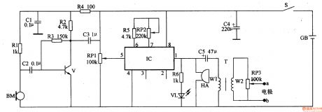
This electronic snore-ceasing equipment circuit is composed of power supply circuit, sound control circuit and electrical pulse generation circuit, it is shown in the figure 9-147.
The sound control circuit is made of microphone BM, resistors R1-R4, capacitors C1, C2 and transistor V.
The electrical pulse generation circuit consists of IC(Y976), resistor R5, potentiometers RP1-RP3, capacitors C3, C5, pulse transformer T and electrodes a,b.
After the power supply switch S is connected, GB's 3V DC voltage is filtered by C4, one path is fed to IC, the other path is current limited by R4 and it is as the working power of sound control circuit.
(View)
View full Circuit Diagram | Comments | Reading(535)
Electronic snore-ceasing equipment 4
Published:2011/6/27 4:15:00 Author:Nicole | Keyword: Electronic snore-ceasing equipment
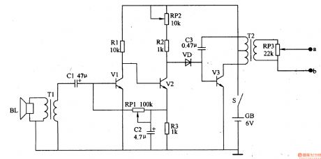
This snoring detection amplifier circuit is composed of loudspeaker BL, coupling transformer T1, capacitors C1, C2, audio amplifier transistors V1, V2, resistors R1-R3 and potentiometers RP1, RP2.
The pulse oscillator is made of diode VD, oscillation tube V3, capacitor C3, pulse transformer T2 and potentiometer RP3.
After the power supply switch S is connected, the snoring detection amplifier circuit starts to work. When there is no snoring, V2's collector has no audio voltage output, V3 is in off state, the electrodes a,b has no stimulation pulse output.
(View)
View full Circuit Diagram | Comments | Reading(524)
Turn-off control circuit
Published:2011/7/4 20:54:00 Author:Christina | Keyword: Turn-off, control circuit
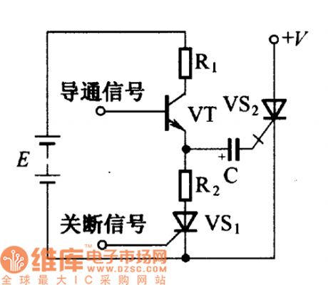
The conduction and turn-off control circuit of the shut-off thyristor is as shown in the figure. When the conduction trigger signalis addedto the base of the semiconductor transistor VT, the VT conducts through the thyristor VS2 which is triggered by the capacitance C. At the same time, the power supply E charges the C through R1. When the turn-off positive pulse comes, the trigger transistor VS1 conducts, the capacitor C discharges through the R2, VS1, VS2(K-G). Because the voltage of the two ends of capacitor C can not change, so the circuit adds the negative pulse to the turn-off thyristor control electrode to turn off the VS2.
(View)
View full Circuit Diagram | Comments | Reading(562)
Electronic snore-ceasing equipment 3
Published:2011/6/27 4:05:00 Author:Nicole | Keyword: Electronic snore-ceasing equipment
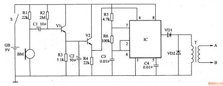
This electronic snore-ceasing equipment circuit is composed of audio detection circuit and stimulation pulse generator circuit.
The audio detection amplifier circuit is made of microphone BM, audio amplifier tubes V1, V2, capacitors C1, C2 and resistors R1-R4.
The stimulation pulse generator circuit consists of time base integrated circuit IC, resistors R5, R6, capacitors C3, C4, diodes VD1, VD2 and pulse transformer T.
After the power supply switch S is connected, this electronic snore-ceasing equipment's audio detection amplifier circuit starts to work.
(View)
View full Circuit Diagram | Comments | Reading(824)
Motor electronic governor controller 7
Published:2011/6/30 22:50:00 Author:Nicole | Keyword: motor, electronic governor controller
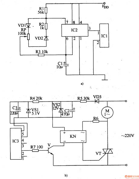
The motor electronic governor controller circuit is composed of wireless remote control transmitting circuit and wireless remote control receiving control circuit, it is shown in the figure 8-64.
The wireless remote control transmitting circuit is made of micro-power wireless remote control transmitting integrated circuit module IC1, time base integrated circuit IC2, diodes VD1, VD2, resistors R1-R3, potentiometer RP and capacitor C1.
The wireless remote control receiving control circuit consists of micro-power wireless remote control receiving integrated circuit module IC3, steady voltage diode VS1, VS2, resistors R4-R7, diode VD3, transistor V, solid state relay KN(SSR) and thyristor VT.
(View)
View full Circuit Diagram | Comments | Reading(941)
Electric snore-ceasing equipment 1
Published:2011/6/30 22:36:00 Author:Nicole | Keyword: Electric snore-ceasing equipment
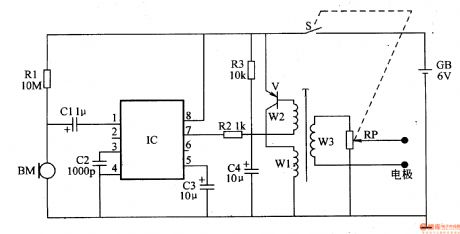
The electric snore-ceasing equipment circuit is composed of snoring detection control circuit and electricity pulse generation circuit, it is shown in the figure 9-143.
The snoring detection control circuit is made of microphone BM, audio level demodulation integrated circuit IC(NJM2027D) and peripheral resistor capacitor component.
NJM2027D contains operation amplifier, detector, electronic switch, Schmitt trigger, output buffer and constant current source, its pin function is: 1 foot is signal input terminal; 2 foot, 3 foot are gain control terminals; 4 foot is grounding terminal; 5 foot is recovery time control terminal; 6 foot, 7 foot are level output terminals; 8 foot is power supply terminal.
(View)
View full Circuit Diagram | Comments | Reading(871)
Macromolecule capacitive humidity sensor structure circuit
Published:2011/6/27 6:45:00 Author:Christina | Keyword: Macromolecule, capacitive, humidity sensor, structure circuit

The macromolecule capacitive humidity sensor structure circuit is as shown in the figure. This kind of humidity sensor is a capacitor, the electrode of the macromolecule film is a layer of very thin metal micropore evaporation film, the water molecules can be adsorbed or released by the macromolecule film through the electrodes of two ends, this makes the macromolecule film dielectric constant change. Because the dielectric constant changes with the relative air humidity, so we can get the relative humidity value by measuring the value of capacitance C. The capacitance value of the humidity sensitive component can be confirmed by the formula of C=εS/d.
(View)
View full Circuit Diagram | Comments | Reading(657)
Thermometer meter slinger 2
Published:2011/6/29 20:14:00 Author:Nicole | Keyword: thermometer, meter slinger

The thermometer meter slinger circuit is composed of power supply circuit and meter slinger timing control circuit, it is shown in the figure 9-135.
The power supply circuit is made of fuse FU, power supply button S(Sa, Sb), resistors R1, R2, capacitors C1, C2, power supply indication LED VL, steady voltage diode VS and rectifier diodes VD1.
The meter slinger timing control circuit consists of resistors R3, R4, potentiometer RP, capacitors C3-C5, relay K and diode VD2.
C3's charge time can be changed by adjusting RP, then it can control M's run time.
(View)
View full Circuit Diagram | Comments | Reading(1090)
Motor two-path insurance starter
Published:2011/7/3 21:42:00 Author:Nicole | Keyword: motor, insurance starter
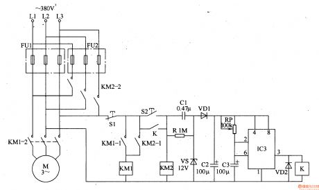
The motor two-path insurance starter circuit is composed of the first path fuse FU1, the second path fuse FU2, stop button S1, starter button S2, AC contactors KM1, KM2, relay K, capacitors C1-C3, diodes VD1, VD2, resistor R, steady voltage diode VS, potentiometer RP and time base integrated circuit IC, it is shown in the figure 8-57.
After IC works, due to the two sides of IC3's voltage can not be suddenly changed, IC's 2 foot, 6 foot are low level, 3 foot output is high level, K is pulled in, the normally open contact is turned on.
(View)
View full Circuit Diagram | Comments | Reading(543)
The Sound control electronic corsage circuit
Published:2011/6/15 1:44:00 Author:Christina | Keyword: Sound control, electronic corsage

This circuit is composed of the sound source amplifier and the LED driving circuit. The microphone is used as the voice detector to change the voice signal into the electrical signal and this electrical signal is amplified by BG1 and BG2 to drive BG3 to turn on the LED.
(View)
View full Circuit Diagram | Comments | Reading(679)
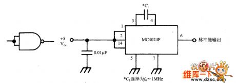
Signal generator simplified with MC4024P circuit
Published:2011/7/4 6:45:00 Author:John | Keyword: Signal Generator
View full Circuit Diagram | Comments | Reading(718)
Motor voltage reducing starter 2
Published:2011/6/29 20:54:00 Author:Nicole | Keyword: motor, voltage reducing starter
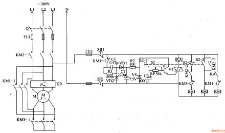
The motor voltage reducing starter circuit is composed of regulated power supply circuit, delay control circuit and control implement circuit, it is shown in the figure 8-56.
The regulated power supply circuit is made of fuses FU1, FU2, stop button S1, capacitors C1, C2, heat relay KR's normally closed contact, resistors R1, R2 and steady voltage diode VS.
The delay control circuit consists of starter control button S2 (S2-1-S2-3), capacitor C3, potentiometer RP, transistor V, TRIAC VT and intermediate relay KA.
When stop button S1 is pressed, the whole circuit is power failure and it stops working.
(View)
View full Circuit Diagram | Comments | Reading(573)
Motor voltage reducing starter 1
Published:2011/6/29 20:24:00 Author:Nicole | Keyword: motor, voltage reducing starter
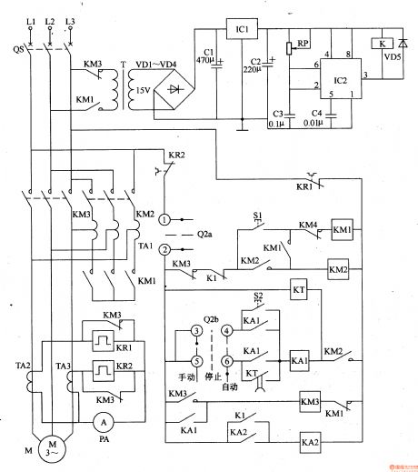
The motor voltage reducing starter is composed of voltage reducing starter control circuit and protection circuit, it is shown in the figure 8-55.
The voltage reducing starter control circuit is made of starter button S1, master controller(Q2a, Q2b), AC contactor KMl-KM3, intermediate relay KA1, KA2, time relay KT, autotransformer TA1.
The protection circuit consists of power transformer T, diodes VDl-VD5, capacitors C1-C3, there terminals steady voltage integrated circuit IC1, potentiometer RP, time base integrated circuit IC2 and relay K.
TA2, TA3 are current transformers, KR1 and KR2 are heat relays, QS is circuit breaker.
(View)
View full Circuit Diagram | Comments | Reading(651)
Motor protector 17
Published:2011/6/27 22:18:00 Author:Nicole | Keyword: Motor, protector

This motor protector circuit is composed of phase pulse detection circuit, monostable trigger circuit, control circuit and power supply circuit, it is shown in the figure 8-53.
The phase pulse detection circuit is made of current transformers TAl-TA3, diodes VDl-VD5, steady voltage diode VS1 and capacitor C1.
The monostable trigger circuit consists of transistor V, resistors R1-R3, potentiometer RP1, capacitors C2-C4, diode VD6 and time base integrated circuit IC1.
The delay control circuit is composed of time base integrated circuit IC2, resistor R4, capacitors C5, C6, diode VD7, LED VL, relay K and AC contactor.
(View)
View full Circuit Diagram | Comments | Reading(630)
| Pages:1624/2234 At 2016211622162316241625162616271628162916301631163216331634163516361637163816391640Under 20 |
Circuit Categories
power supply circuit
Amplifier Circuit
Basic Circuit
LED and Light Circuit
Sensor Circuit
Signal Processing
Electrical Equipment Circuit
Control Circuit
Remote Control Circuit
A/D-D/A Converter Circuit
Audio Circuit
Measuring and Test Circuit
Communication Circuit
Computer-Related Circuit
555 Circuit
Automotive Circuit
Repairing Circuit
