Circuit Diagram
Index 1625
Motor protector 18
Published:2011/6/27 22:26:00 Author:Nicole | Keyword: Motor, protector
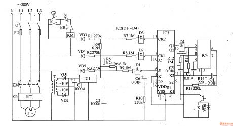
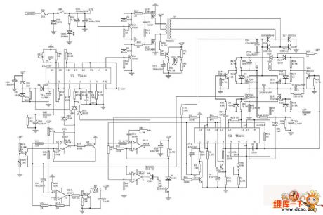
This motor protector circuit is composed of power supply circuit, phase sequence detection circuit, monostable circuit and control implement circuit, it is shown in the figure 8-54.
The power supply circuit is made of power transformer T, rectifier diodes VD1, VD2, capacitors C1, C2 and there terminals steady voltage integrated circuit IC1.
The phase sequence detection circuit consists of diodes VD3-VD5, resistors R1-R10, capacitor C6, four NAND gates Schmitt trigger integrated circuit IC2(D1-D4) and double JK master-slave trigger integrated circuit IC3.
The monostable circuit is composed of resistors R11-Rl3, capacitors C3-C5 and time base integrated circuit IC4.
(View)
View full Circuit Diagram | Comments | Reading(929)
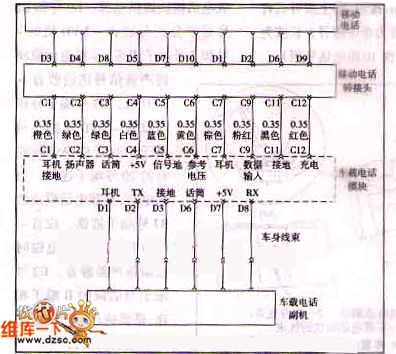
Shanghai Buick Regal phone system control circuit
Published:2011/7/4 11:02:00 Author:John | Keyword: phone system
View full Circuit Diagram | Comments | Reading(709)
Standard PAL standard color decoder frame circuit
Published:2011/7/4 10:59:00 Author:John | Keyword: decoder
View full Circuit Diagram | Comments | Reading(970)
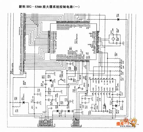
Shinco HG-5300 amplifier system control circuit (a)
Published:2011/7/4 10:59:00 Author:John | Keyword: amplifier system
View full Circuit Diagram | Comments | Reading(1151)
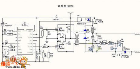
Electronic fishing device (high power) circuit
Published:2011/7/4 10:57:00 Author:John | Keyword: Electronic fishing device, fishing device
View full Circuit Diagram | Comments | Reading(4106)
The Transistor AK90GB80 and AK90HB120 internal circuits
Published:2011/6/15 1:44:00 Author:Christina | Keyword: Transistor, internal circuit
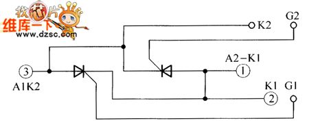
The Transistor AK90GB80 and AK90HB120 internal circuits:
(View)
View full Circuit Diagram | Comments | Reading(435)
Inverter circuit (150W)
Published:2011/7/4 10:55:00 Author:John | Keyword: Inverter
View full Circuit Diagram | Comments | Reading(2391)
The Differential amplifier circuit
Published:2011/6/15 1:44:00 Author:Christina | Keyword: Differential, amplifier

The basic form requirements of the circuit:
The parameters of the two circuits are completely symmetry. Also the temperature features of the two tubes are completely symmetry.
Working principle: when you input the signal Ui=0, the two tubes have the same current, also the collector electrode potential, so the output voltage Uo=UC1-UC2=0. When the temperature is increasing, the currents of the two tubes increase too, and the collector electrode potentials reduce, because they are in the same temperature environment, so the two tube have the same variation values of current and voltage, the output voltage is still zero. (View)
View full Circuit Diagram | Comments | Reading(679)
The OTL power amplifier circuit
Published:2011/6/15 1:44:00 Author:Christina | Keyword: OTL, power amplifier

Figure: The OTL power amplifier circuit (View)
View full Circuit Diagram | Comments | Reading(2497)
The Sony KV-25G protection circuit
Published:2011/6/15 1:44:00 Author:Christina | Keyword: Sony, protection circuit
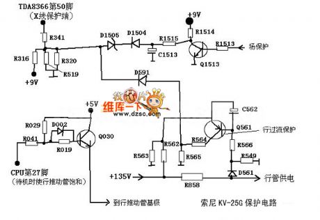
The Sony KV-25G protection circuit is as shown:
(View)
View full Circuit Diagram | Comments | Reading(600)
The High-speed TTL probe circuit
Published:2011/6/15 1:43:00 Author:Christina | Keyword: High-speed, TTL, probe

The RS flip-flop which is composed of the NAND gates can detect the narrow pulse, and the narrowest pulse width is the total delay time (about 30ns) of the flip-flop's two NAND gates. When the pulse appears, the circuit will change and the LEDs display the output state of flip-flop. You must use the K after detecting the pulse; By resetting the circuit and according to the choice of K1, this circuit can response the positive pulse or negative pulse.
(View)
View full Circuit Diagram | Comments | Reading(691)
Motor Control Circuit of VFC320
Published:2011/6/26 5:04:00 Author:Michel | Keyword: Motor Control, Circuit

The aboved picture is the motor control circuit composed of VFC320.Tachogenerator G outputs AC current which is correspondent to motor speed.VTl circuit converts it into the narrow negative pulse and trigger frequency/voltage converter VFC320.There are operational amplifiers in VFC320 chip and they are used as the integratorof the speed control loop. When integrator receives the input control voltage of the corresponding average current of equal and opposite direction and the single trigger pulse current added to frequency/voltage converter feedback loop reaches balanced condition.DRVlO1 driver is used in motor and its maximum output current is 1.9 A and which is enough to drive the ordinary motor. (View)
View full Circuit Diagram | Comments | Reading(1397)
single-chip True RMS power measured system AD8362 true RMS level measuring meter circuit
Published:2011/7/4 10:53:00 Author:John | Keyword: single-chip True RMS, power measured system, true RMS level measuring device
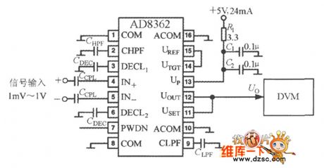
AD8362 True RMS level measuring meter circuit is as shown. The AD8362's output voltage is directly sent to the digital voltmeter (DVM). It should be noted that it belongs to the voltage level meter because the DVM reading is proportional to the measured rms voltage’s logarithm. And the meter’s display unit is dBv. During the measurement for high frequency RF input signal, the following measures should be taken: one is to increase the input decoupling capacitor (or RC decoupling network) and the other is to minimize the length of input signal lead, decoupling capacitors lead and ground wire.
(View)
View full Circuit Diagram | Comments | Reading(2415)
The TIL probe circuit
Published:2011/6/15 1:43:00 Author:Christina | Keyword: TIL, probe

If the polarity switch is in the position as shown, so when the input probe receives the low-level (negative) pulse, the LED turns on until the circuit is reset. If you push switch to another position, and there is high-level voltage or +5V input pulse, the LED turns on too.
(View)
View full Circuit Diagram | Comments | Reading(709)
Single Input CA3140 Instrument Amplifier Circuit
Published:2011/7/1 18:54:00 Author:Michel | Keyword: Single Input, Instrument Amplifier, Circuit
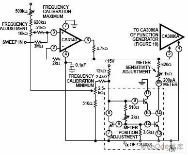
Picture:Single Input CA3140 Instrument Amplifier Circuit (View)
View full Circuit Diagram | Comments | Reading(959)
monolithic true RMS power measurement system AD8362 input protection circuit
Published:2011/7/4 10:45:00 Author:John | Keyword: monolithic true RMS, power measurement system, input protection
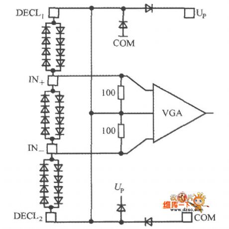
AD8362 input protection circuit is as shown. Two anti-pole composite diodes are set between the IN + and IN- in parallel, which can play a role of being with clamping protection. It also can avoid input of the sensor to damage the chip due to the instantaneous high voltage. Besides, the diode clamp protection circuit is designed to be placed in the pine between the DECL1 and IN +, IN- and the DECL2.
(View)
View full Circuit Diagram | Comments | Reading(684)
Shuangzhen Dalian Supplies Japan Anti-static Nylon Board
Published:2011/6/24 11:09:00 Author:Michel | Keyword: Shuangzhen Dalian , Japan, Anti-static, Nylon Board

Shuangzhen Dalian supplies Japan Importing anti-static nylon board.Shenzhen Shuangzhen Electronic Co., Ltd is found in Feb. 2007 which has office and warehouses. We are specialied in providing anti-static organic glasses.We devote to providing high-quality industrial products to meet the special needs of high-tech times industry and provide good after-sales service.
Features
MC501CDR6 the filling material of anti-static nylon board is even, anti-static value of all nylon parts are the same.Mechanical processing or after surface wearing, anti-static value has no change. (View)
View full Circuit Diagram | Comments | Reading(674)
The Calendar Clock Circuit
Published:2011/6/15 1:43:00 Author:Christina | Keyword: Calendar, Clock

The FCM CT7001 clock chipis produced by the Fairchild company, and this device let the 6-digit & 7-segment LED display the time of 12h or 24h, and also has the function of 28/30/31 calendar and alarm. The (3)(5)(10)(12) of the SN74591 driver chip connect to (11) by a 150Ω resistor. Generally the RL is 2.7KΩ, it limits the LED current less than 5mA. (View)
View full Circuit Diagram | Comments | Reading(1707)
The Circuit Of Symmetry Amplifier
Published:2011/6/15 1:42:00 Author:Christina | Keyword: Symmetry Amplifier

The Circuit Of Symmetry Amplifier is as shown.
Welcome to reprint, the information is from the Weiku Electronic Market Network (www.dzsc.com). (View)
View full Circuit Diagram | Comments | Reading(1280)
The electric switch circuit of touch type (4)
Published:2011/7/4 4:28:00 Author:Seven | Keyword: electric switch circuit, touch type
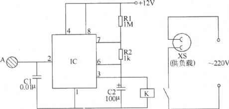
The following is to introduce an electric switch circuit of touch type which is made of 555 time-based integrated circuit, it characterizes convenient operation(by touching), delaying the auto shut-off and so on, which can be used to control the kitchen ventilator, toilet ventilator and lamps in the stairway, corridor and other place. This electric switch circuit of touch type consists of the touch electrode pole chip A, the time-based integrated circuit IE, the capacitors E1 and C2, the resistance R1 and R2, relay K and so on.
By adjusting the volume of C1, the sensitivity of the single stable trigger can be changed. (View)
View full Circuit Diagram | Comments | Reading(1315)
| Pages:1625/2234 At 2016211622162316241625162616271628162916301631163216331634163516361637163816391640Under 20 |
Circuit Categories
power supply circuit
Amplifier Circuit
Basic Circuit
LED and Light Circuit
Sensor Circuit
Signal Processing
Electrical Equipment Circuit
Control Circuit
Remote Control Circuit
A/D-D/A Converter Circuit
Audio Circuit
Measuring and Test Circuit
Communication Circuit
Computer-Related Circuit
555 Circuit
Automotive Circuit
Repairing Circuit
