
Circuit Diagram
Index 1636
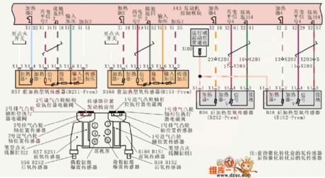
Shanghai Buick Royaum V63.6L car oxygen sensor circuit diagram
Published:2011/6/24 4:19:00 Author:Nicole | Keyword: Shanghai Buick Royaum, car, oxygen sensor
View full Circuit Diagram | Comments | Reading(498)
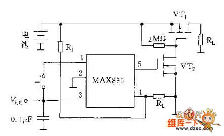
Monitoring battery low voltage turning off power supply circuit diagram
Published:2011/6/24 8:29:00 Author:Nicole | Keyword: Monitoring, battery, low voltage, power supply
View full Circuit Diagram | Comments | Reading(516)
Numerical control reference voltage source cirucit diagram with 0~9.99V output voltage
Published:2011/6/24 8:24:00 Author:Nicole | Keyword: numerical control, reference voltage source, 0~9.99V output voltage

View full Circuit Diagram | Comments | Reading(485)
DC switch circuit
Published:2011/7/3 19:06:00 Author:Christina | Keyword: DC, switch circuit

The DC switch circuit which is composed of the turn-off thyristor is as shown in the figure. The VD is the absorption diode, the C is the absorption capacitance, the R is the discharge resistance.
DC switch circuit (View)
View full Circuit Diagram | Comments | Reading(548)
simple audio amplifition(LM307、μA741) circuit
Published:2011/7/1 0:08:00 Author:chopper | Keyword: simple, audio amplifition

(View)
View full Circuit Diagram | Comments | Reading(917)
BCD binary number convert circuit diagram
Published:2011/6/24 8:23:00 Author:Nicole | Keyword: binary, number, convert

View full Circuit Diagram | Comments | Reading(4881)
OPA2111 balanced stereo preamplifier circuit
Published:2011/7/1 0:26:00 Author:chopper | Keyword: balanced, stereo, preamplifier

Figure shows a balanced stereo preamplifier circuit. Figure (a) is for the left channel preamplifier circuit,and Figure (b) is for the right channel preamplifier. The circuit uses a dual op-amp OPA2111. Left and right channels, respectively, use a op-amp of dual op-amp OPA2111.Thus the left and right channel have a good matching (gain differ is 3dB, bias differ is 0.5pA, drift differ is ± 0.5μV / ℃), and it is appropriate to constitutes a balanced stereo preamplifier. (View)
View full Circuit Diagram | Comments | Reading(1487)
HM927OD IC Typical Application Circuit
Published:2011/7/1 4:24:00 Author:Robert | Keyword: IC, Typical, Application

The HM927OD is a DTMF double-tone multi-frequency caller ID decoding IC produced by the Hualong company in Chinese Taiwan area. It is widely used in many kinds of caller ID telephones such as the TCL series.
The double-tone multi-frequency caller ID decoding typical application circuit composed of the HM927OD IC is shown in the picture.
The picture shows the HM927OD IC's typical application circuit. (View)
View full Circuit Diagram | Comments | Reading(652)
HT12C IC Typical Application Circuit
Published:2011/7/1 4:10:00 Author:Robert | Keyword: IC, Typical, Application

The HT12C is a fan single-chip remote-control coding IC which is widely used in the remote-control systems in many kinds of fans.
The remote-control coding typical application circuit composed of the HT12C IC is shown in the picture.
The picture shows the HT12C IC's typical application circuit. (View)
View full Circuit Diagram | Comments | Reading(1145)
HT92050 IC Typical Application Circuit
Published:2011/7/1 8:44:00 Author:Robert | Keyword: IC, Typical, Application

The HT92050 is communication single-chip micro-computer IC which is used in many kinds of caller ID telephones.
The dialing control system typical application circuit composed of HT92050 IC is shown in the picture.
The picture shows the HT92050 IC's typical application circuit. (View)
View full Circuit Diagram | Comments | Reading(720)
HT9245DL IC Typical Application Circuit
Published:2011/7/1 7:41:00 Author:Robert | Keyword: IC, Typical, Application

The HT9245DL is a single-chip micro-computer which is widely used in caller ID cordless or corded phones. For example, the Qiaoxing series IC card telephones and so on.
The dialing system typical application circuit composed of HT9245DL IC is shown in the picture.
The picture shows the HT9245DL IC's typical application circuit. (View)
View full Circuit Diagram | Comments | Reading(853)
HT9302D IC Typical Application Circuit (1)
Published:2011/7/1 7:35:00 Author:Robert | Keyword: IC, Typical, Application

The HT9302D is a communication single-chip micro-computer IC which is widely used in the dialing circuit in the communication equipments such as cordless phones and corded phones, caller ID phones.
The dialing control system typical application circuit composed of HT9302D IC is shown in the picture.
The picture shows the HT9302D IC's typical application circuit. (View)
View full Circuit Diagram | Comments | Reading(1248)
HT9302D IC Typical Application Circuit (2)
Published:2011/7/1 7:36:00 Author:Robert | Keyword: IC, Typical, Application

The HT9302D is a communication single-chip micro-computer IC which is widely used in the dialing circuit in the communication equipments such as cordless phones and corded phones, caller ID phones.
The dialing control system typical application circuit composed of HT9302D IC is shown in the picture.
The picture shows the HT9302D IC's typical application circuit. (View)
View full Circuit Diagram | Comments | Reading(1122)
X0640CE Field Scanning Output IC Internal Circuit
Published:2011/7/1 7:08:00 Author:Robert | Keyword: Field, Scanning, Output, IC, Internal

The 1X0640CE is a field scanning output IC produced by Japanese SHARP company which is widely used in many kinds of domestic and imported color TV sets.
The 1X0640CE IC has internal field excitation circuit, field output circuit, vertical blanking circuit and overheat protection circuit. Its internal circuit is shown in the picture.
The picture shows the 1X0640CE IC's internal circuit. (View)
View full Circuit Diagram | Comments | Reading(725)
The infrared monitor wireless alarm circuit
Published:2011/7/1 22:17:00 Author:Borg | Keyword: infrared monitor, wireless alarm
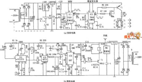
In the figure is the infrared monitor wireless alarm circuit. The circuit consists of the infrared monitoring emitter and the infrared reception circuit, two parts in total, which are shown in figure (a) and figure (b) respectively. Figure (a) adopts two CMOS 555 chips (or one 556), IC1 and IC2, the two outputs the waveforms of 1.5KHz and 35KHz respectively, of which the 1.5KHz square wave is used to modulate the loading wave. In the figure, IC1 is connected as a multi-resonance oscillator, whose oscillating frequency is 1.5KHz, and the corresponding charge/discharge time is decided by the time constant. The duty cycle of the square wave output by IC1 is 1:3 (160μs:500μs).
(View)
View full Circuit Diagram | Comments | Reading(635)
The non-source current/voltage separation amplifier circuit of transformer coupling type
Published:2011/7/1 21:56:00 Author:Borg | Keyword: amplifier circuit, transformer coupling
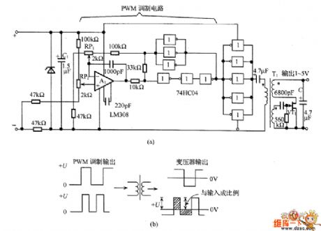
In the figure is the non-source current/voltage separation amplifier circuit of transformer coupling type. In the circuit, the bias branch of the input signal is taken as the power supply of the circuit, the input signal is a DC current of 4~20mA. The circuit is in PWM modulation, the total current consumption is under 4mA, and the circuit has no power for transformer coupling.
PWM modulated signal is split in two signals of the same size by the transformer, see as the sloped line part of figure (b). The single peak value and the input signal of pulse waveform are in the positive ratio. (View)
View full Circuit Diagram | Comments | Reading(946)
DJ1001-063 Fan Single-Chip Micro-Computer Integrated Circuit
Published:2011/7/3 9:53:00 Author:Robert | Keyword: Fan, Single-Chip, Micro-Computer, Integrated


The DJ1001-063 is a fan single-chip micro-computer integrated circuit produced by Japanese NEC company which is widely used in many kinds of fan control circuits, such as the bats series.
1.Its functional features.
The DJ1001-063 IC has internal reset circuit, clock oscillation circuit, zero-crossing detecting circuit, LED display driving circuit, fan speed control circuit, key-bit scanning pulse generating circuit, key-bit command decoding circuit and other some auxiliary functional circuits.
2.Its pin's function and data
The DJ1001-063 IC uses 24-pin dual-row package and its pin's function is listed in table 1 and its working voltage is listed in table 2.
The table 1 shows the DJ1001-063 IC's pin's functions.
The table 2 shows the DJ1001-063 IC'w working voltage.
3.Typical application circuit
The fan control circuit typical application circuit composed of the DJ1001-063 IC is shown in picture 1.
The picture 1 shows the DJ1001-063 IC's typical application circuit. (View)
View full Circuit Diagram | Comments | Reading(623)
The circuit of the 3-phase motor powered by the single phase
Published:2011/7/1 22:30:00 Author:Borg | Keyword: 3-phase motor, single phase

To run a 3-phase motor with a single power supply, we just need a proper phase drifting capacitor, the methods are as follows: for the motor of star connection, whose connection is shown in figure 1; for the motor of triangular connection, the connection is shown in figure 2. According to the practice, the value of the volume in the phase-drifting capacitor should be equal to the product of 0.07 and the motor power, for example, the power of the motor is 150W, and the volume of the capacitor is equal to 0.07 x 150=10.5uF, so the need can be met by connecting two sunlight lamps (4.75μF) in parallel way.
(View)
View full Circuit Diagram | Comments | Reading(2031)
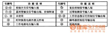
E0227 Range Hood Single-Chip Micro-Computer Integrated Circuit
Published:2011/7/3 9:20:00 Author:Robert | Keyword: Range Hood, Single-Chip, Micro-Computer, Integrated


The E0227 is a range hood single-chip micro-computer IC which is used in many brands of range hoods.
1.Its functional features.
The E0227 IC uses 18-pin dual inline plastic package and its pin's functions are listed in table 1.
The table 1 shows the E0227 IC's pin's functions.
2.Typical application circuit.
The range hood control system typical application circuit composed of the E0227 IC is shown in the picture 1.
The picture 1 shows the range hood control system typical application circuit composed of E0227 IC. (View)
View full Circuit Diagram | Comments | Reading(686)
The transformer coupled current/current separation amplifier circuit
Published:2011/7/1 22:07:00 Author:Borg | Keyword: transformer, amplifier circuit, current separation
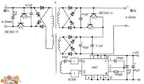
In the figure is the transformer coupled current/current separation amplifier circuit. In the circuit, the Darlington-connected transistors (VT1 and VT2) are as the current buffering circuit, which uses the DC/DC converter to convert the primary current signal of the transformer T1 into the AC signal, and then it is sent to the secondary stage. The secondary stage converts the diode bridge current into the DC current signal. As the signal is the current signal, which is not affected by the UF of the diode. The secondary stage also adopts the transistors (VT3 and VT4) as the buffer.
(View)
View full Circuit Diagram | Comments | Reading(637)
| Pages:1636/2234 At 2016211622162316241625162616271628162916301631163216331634163516361637163816391640Under 20 |
Circuit Categories
power supply circuit
Amplifier Circuit
Basic Circuit
LED and Light Circuit
Sensor Circuit
Signal Processing
Electrical Equipment Circuit
Control Circuit
Remote Control Circuit
A/D-D/A Converter Circuit
Audio Circuit
Measuring and Test Circuit
Communication Circuit
Computer-Related Circuit
555 Circuit
Automotive Circuit
Repairing Circuit