
Circuit Diagram
Index 1621
Mosfet 50 W Audio Power Amplifier Circuit
Published:2011/7/1 3:44:00 Author:Joyce | Keyword: Mosfet , 50 W, Audio, Power Amplifier

As shown in the figure is a Mosfet 50 W audio power amplifier circuit. (View)
View full Circuit Diagram | Comments | Reading(8187)
Mosfet 80 W Audio Power Amplifier Circuit
Published:2011/7/1 3:42:00 Author:Joyce | Keyword: Mosfet, 80 W , Audio , Power Amplifier

As shown in the figure is a Mosfet 80 W audio power amplifier circuit. (View)
View full Circuit Diagram | Comments | Reading(7517)
500W Transistor Power Amplifier Circuit
Published:2011/7/1 3:40:00 Author:Joyce | Keyword: 500W , Transistor , Power Amplifier

As shown in the figure is a 500W transistor power amplifier circuit. (View)
View full Circuit Diagram | Comments | Reading(14157)
Benz fault diagnosis process circuit
Published:2011/7/4 21:16:00 Author:Christina | Keyword: Benz, fault diagnosis, process circuit
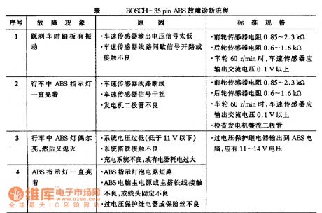
Benz fault diagnosis process circuit
(View)
View full Circuit Diagram | Comments | Reading(416)
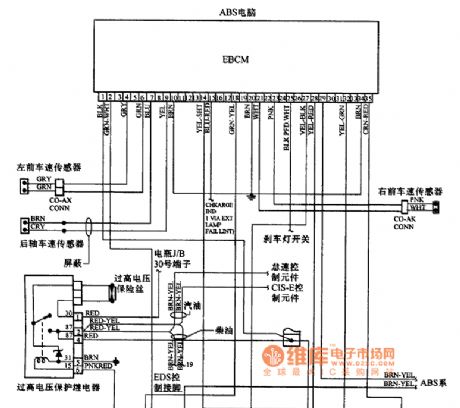
BENZ BOSCH-35pin ABS system circuit
Published:2011/7/4 21:15:00 Author:Christina | Keyword: BENZ, BOSCH-35pin, ABS, system circuit

BENZ BOSCH-35pin ABS system circuit
(View)
View full Circuit Diagram | Comments | Reading(608)
BENZ 300 and 260 series ABS system circuit
Published:2011/7/4 21:14:00 Author:Christina | Keyword: BENZ, 300, 260 series, ABS, system circuit
BENZ 300 and 260 series ABS system circuit
(View)
View full Circuit Diagram | Comments | Reading(414)
Photosensitive resistor operating indication circuit
Published:2011/7/4 21:03:00 Author:Christina | Keyword: Photosensitive resistor, operating, indication circuit
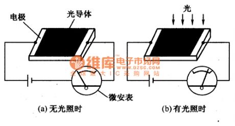
The working principle of the photosensitive resistor is the photoconductive effect. When the semiconductor materials are illuminated by the light, if the energy of the incident photons is larger than the prohibited bandwidth of the semiconductor, the number of the semiconductor internal carrier increases, so the conductivity of the semiconductor changes to reduce the resistance, this kind of physical phenomena is the photoconductive effect.
Figure: The Photosensitive resistor operating indication circuit
The photosensitive resistor in this figure has large resistance when there is no illumination, the resistance of it is in the range of 1 to 100MΩ. Because the resistance of the photosensitive resistor is too large, so the circuit current is small.
(View)
View full Circuit Diagram | Comments | Reading(543)
Quartz crystal resonator equivalent circuit
Published:2011/7/4 20:47:00 Author:Christina | Keyword: Quartz crystal, resonator, equivalent circuit
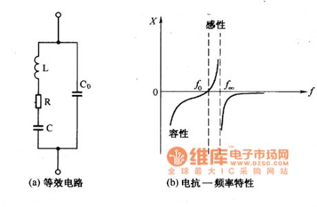
The quartz crystal resonator equivalent circuit and the characteristic curve are as shown in figure 1. In the equivalent circuit, C0 is the capacitance between the two electrodes when the quartz crystal is working, it is called the electrostatic capacitive. The L and C are the equivalent parameters when the quartz crystal is resonating, R is the equivalent resistance, it represents the friction loss when the quartz crystal is oscillating, its value is about 100 Ω.
Figure 1 The quartz crystal resonator equivalent circuit and the characteristic curve
From the quartz crystal reactance - frequency characteristic curve we can see, the quartz crystal has two inherent frequencies, one is the L, C series resonance frequency f0, another is the L, C, Co parallel resonant frequency f∞. Because the Co is one hundred times larger than C, so the frequency of it is decided by the L, C parameters. (View)
View full Circuit Diagram | Comments | Reading(1262)
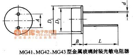
MG41, MG42, MG43 metal glass package photoconductive resistors circuit
Published:2011/7/4 20:36:00 Author:Christina | Keyword: metal, glass, package, photoconductive resistors
View full Circuit Diagram | Comments | Reading(453)
MG41, MG43 metal glass package double photoconductive resistors circuit
Published:2011/7/4 20:23:00 Author:Christina | Keyword: metal, glass, package, double photoconductive resistors

MG41, MG43 metal glass package double photoconductive resistors circuit (View)
View full Circuit Diagram | Comments | Reading(527)
555 Audio Oscillator circuit driven by radiofrequency
Published:2011/7/5 0:14:00 Author:Zoey | Keyword: 555 Audio Oscillator circuit, radiofrequency


As shown in the picture 3-14, a 555, R1, RP1,C1 and other parts constitute a controllable audio oscillator, the frequency ofparameter in the picture ranges from 600Hz~20kHz,and it can be selected by adjusting RP1.
Whether the oscillator will oscillate or not is determined by the level on reset terminal of pin 4. Without radio-frequency signal, pin 4 will be in low level and 555 will cease to oscillate; when radiofrequency signal is available, it will be detected by the radiodetector diode D1, and the signal will be sent to pin 4, when the signal level is higher than 1V, the oscillator will oscillate, and the speaker will give out an audio signal that has been adjusted.
Figure 3-14 Audio oscillator circuit driven by radio-frequency Figure3-15 Oscillator circuit in synchronism with clock
(View)
View full Circuit Diagram | Comments | Reading(1168)
11 basic circuits of 555 multi-vibrator
Published:2011/7/5 0:14:00 Author:Zoey | Keyword: 11 basic circuits, 555 multi-vibrator


As shown in picture (C), after adding the conduction diode D1 and D2, the charge and discharge time constantwill be separately adjusted. If R1=R2, the duty cycle is 50%. This goes for picture (D), too.
The charge and discharge capacitance arrive at C1 via C, so C1 can get charged to 2/3 VDD quickly and the upper comparator will be turnover and replaced. After being replaced, C will discharge and the voltage of its two terminals will fall to 1/3 VDD, 555 will deposit.
The oscillator frequency in picture (f) is higher than that in (a)~(b);
The circuit in picture (g) can obtain negative narrow pulse;
the circuit in picture(h) can produce a pulse square wave of a 50% duty cycle;
the circuit in picture (i) has an adjustable charge and discharge time constant;
the circuit in picture (j) has independent charge and discharge time constant.
When circuit in picture (k) is galvanized, pin 2and pin 6 will be in high level, 555 will deposit and pin 3 will be in low level of 0, then the discharge tube in IC will be saturated and conducted. f and R will be in direct ratio while f and L will be in inverse ratio. (View)
View full Circuit Diagram | Comments | Reading(1139)
Adjustable Duty cycle 555 Square wave Generator
Published:2011/7/4 22:11:00 Author:Zoey | Keyword: Adjustable, Duty cycle, 555, Square wave Generator

As shown in the figure 3-4, as soon as the voltage VDD is connected, the oscillator starts up. At the beginning of being powered, as the voltage can not be changed suddenly, that is, the starting level of pin 2 is the earth potential, in order to position 555 and leave pin 3 in a state of high level. C charges itself through Ra and D1, the charge time
tc=0.693RaC.
When the voltage on C reaches threshold level, that is 2/3 VDD, pin 3 is in a low level. At that time, C discharges through the discharge tube in D1,Rb and 555. The discharge time
Td=0.693RbC.
Suppose the duty cycle is D, then
D=tc/Td=Ra/Ra+Rb
Adjust RP1, when the center part slide to top,
Dmin=tc/T=1k/1k+11K≈8.3%
When center part of RP1 slide to bottom,
Dmax=11K/11K+1K≈91.7%
Figure3-4 Adjustable Duty cycle Square wave Generator
Figure3-5 Large-scalechangeable Duty cycle Square wave Generator (View)
View full Circuit Diagram | Comments | Reading(1670)
555 Oscillator circuit in synchronism with clock
Published:2011/6/24 2:46:00 Author:Zoey | Keyword: 555Oscillator circuit, in synchronism with clock


The oscillation of the oscillator is determined by the level of pin 4 in the reset terminal. Without RF signal, pin 4is in low level and 555 ceases to oscillate. When specified RF signal is available, the wave is detected by detector diode D1 and the video signal is placed on pin 4. When signal level turns to be higher than 1V, it starts to oscillate, and the speaker will sent out audio signal adjusted.
Figure3-14 Audio oscillator Circuit driven by RF Figure 3-15 Oscillator circuit in synchronism with clock
As shown in the figure 3-14, 555,R1, RP1 and C1 constitute a controllable audio oscillator, and f=1.44/(R1+2RP1)C1, frequency of parameter in the picture is between 600Hz~20kHz, which can be adjusted by RP1.
(View)
View full Circuit Diagram | Comments | Reading(790)
Touching delay lamp switch circuit(4)
Published:2011/7/1 2:32:00 Author:Ecco | Keyword: Touching , delay lamp , switch
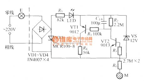
The chart shows the touching delay lamp switch circuit with two-wire connection, which is characterized by: the circuit design is reasonable, the individual discrete small, the delay time error between the manufactured goods is low, so it is suitable for the factory for mass production.
(View)
View full Circuit Diagram | Comments | Reading(590)
Touching delay lamp switch circuit(3)
Published:2011/7/1 2:22:00 Author:Ecco | Keyword: Touching , delay lamp , switch
View full Circuit Diagram | Comments | Reading(864)
Touching delay lamp switch circuit(2)
Published:2011/7/1 2:29:00 Author:Ecco | Keyword: Touching , delay lamp, switch
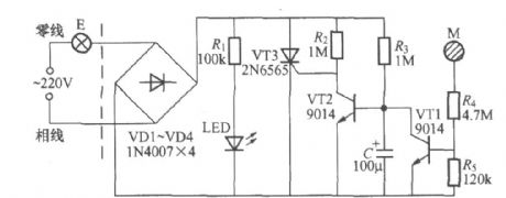
The chart shows the touching delay lamp switch circuit with two-wire connection, which can directly replace ordinary light switch without having to change the interior of the original wiring, so it is suitable for stairs or walkway lighting switches as they could be automatically turned off when going to bed at night. The relationship between C1 charge and discharge circuit and the delay time:
(View)
View full Circuit Diagram | Comments | Reading(688)
Touching delay lamp switch circuit(1)
Published:2011/7/1 2:26:00 Author:Ecco | Keyword: Touching , delay lamp, switch
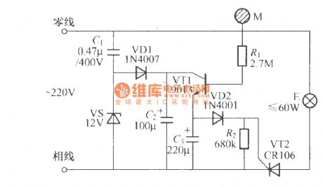
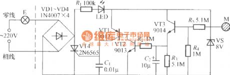
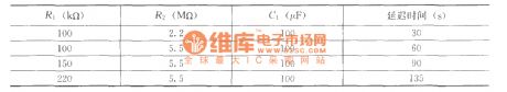
Touching delay lamp switch circuit is shown as the chart, as long as to touch the electrode M, the E will be lit, then after a short interval time, the light will automatically turn off. Using the icon data will make the delay time be about 90s. For extending the time, it is best to increase the capacity of C3; the other hand, it can reduce the C3 or the value of R2.
(View)
View full Circuit Diagram | Comments | Reading(525)
Touching adjustable timing light circuit (2)
Published:2011/7/1 2:52:00 Author:Ecco | Keyword: Touching, adjustable , timing light

The chart shows is a practical touching adjustable timing light circuit which is composed of NE555 time-base circuit, and the timing time is adjustable in 10 ~ 60min. As long as to reach the regular time, the light will be turned off. In the prescribed time period, you can also turn off the lights by touching way to achieve early action, and the circuit is very suitable for desk lamps.
(View)
View full Circuit Diagram | Comments | Reading(2851)
Touching adjustable timing light circuit (1)
Published:2011/7/1 2:50:00 Author:Ecco | Keyword: Touching , adjustable , timing light

The chart shows a practical touching adjustable timing light circuit with timer time being adjustable in 1h. As long as alarm time reached, the light E is turned off, it can be used to time and turn off lights and other housing appliances.
(View)
View full Circuit Diagram | Comments | Reading(1506)
| Pages:1621/2234 At 2016211622162316241625162616271628162916301631163216331634163516361637163816391640Under 20 |
Circuit Categories
power supply circuit
Amplifier Circuit
Basic Circuit
LED and Light Circuit
Sensor Circuit
Signal Processing
Electrical Equipment Circuit
Control Circuit
Remote Control Circuit
A/D-D/A Converter Circuit
Audio Circuit
Measuring and Test Circuit
Communication Circuit
Computer-Related Circuit
555 Circuit
Automotive Circuit
Repairing Circuit