
Circuit Diagram
Index 1638
The circuit design reference diagram
Published:2011/7/1 23:54:00 Author:Borg | Keyword: circuit design, reference diagram
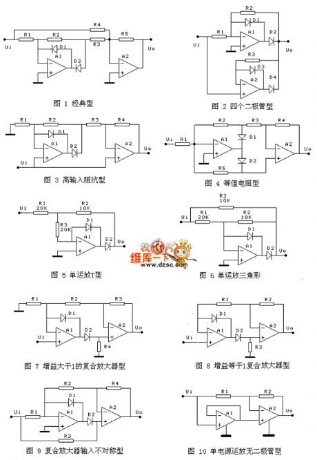
The precise full-wave rectifier circuit in the figure is named by myself, which is only for distinguishing; unless there are special instructions, or the gains are all designed according to 1. In figure 1 is the most classical circuit, whose virtue is that it can connect with a filter capacitor in the parallel way on R5. The coupling relation is R1=R2, R4=R5=2R3. It can also adjust the gain by changing R5. The circuit in figure 2 characterizes few resistors, which only requires R1=R2. The circuit in figure 3 characterizes high input impedance, the coupled resistor requires R1=R2, R4=2R3. All the coupled resistors in figure 4 are the same, and the gain can be adjusted by changing R1.
(View)
View full Circuit Diagram | Comments | Reading(569)
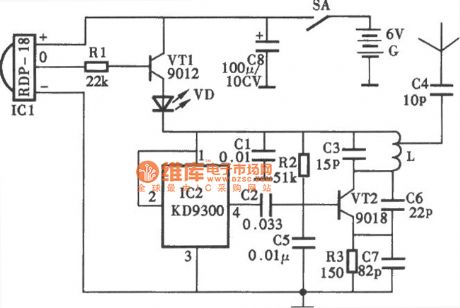
the circuit of whether rooster or hen discriminator(2)
Published:2011/6/28 8:06:00 Author:Ariel Wang | Keyword: rooster, hen , discriminator(
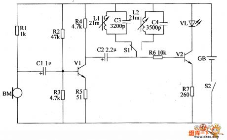
When the mains switch gets through,every circuit of the whole machine is conducted to work.The microphone BM converts the recieved sound signal of the chickling into the electric signal.It is amplified by V2.Then it goes into the selective amplifier which consists of selective circuit and LED drived circuit.Then it is selected and amplified.When S1 is pressed,the 4.8kHz selective circuit works.When S1 isn't pressed,5.2kHz selective circuit works.If VL doesn't lighted when S1 is pressed.Then VL is lighted if S1 is not pressed.It imforms the chickling is hen. (View)
View full Circuit Diagram | Comments | Reading(499)
The FET wave chopping transformer coupling separating amplifier circuit
Published:2011/7/2 2:12:00 Author:Borg | Keyword: transformer, separating amplifier circuit
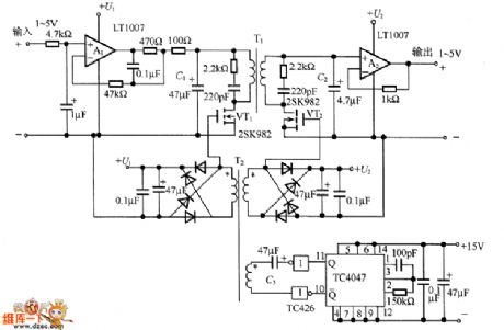
In the figure is the FET wave chopping transformer coupling separating amplifier circuit. The 1~5V DC input signal is impedance-converted by the buffer amplifier A1, and then turned into the AC signal by VT1 chopper, the AC signal is sent to the second stage by transformer T1. After that, it engages in the VT2 ON/OFF control at the second stage and it is rectified synchronously, and then it is changed in to a DC voltage signal which is proportional to the DC voltage signal.
In the circuit, TC4047 composes the multi-resonance oscillator, which generates the 25kHz square wave, and the wave motivates the driver TC426 of VT1 and VT2. (View)
View full Circuit Diagram | Comments | Reading(1419)
Intelligent charging system schematic block circuit
Published:2011/7/2 3:09:00 Author:John | Keyword: charging system, schematic block

The chip is the three-terminal isolated PWM monolithic switching power supply integrated circuit, which is produced by the United States Powergration. It integrates the PWM IC and FET in the same chip, thus occupying all the require functionality of the PWM switching power supply. High-frequency transformer is able to isolate the output termination from the grid completely. This also can achieve the isolated single-chip switching power supply integration of a non-frequency transformer. The entire circuit is with a wide range of output power, low cost, high degree integration and simple circuit design and other advantages.
(View)
View full Circuit Diagram | Comments | Reading(995)
Human control electric fan circuit
Published:2011/6/27 22:16:00 Author:chopper | Keyword: Human control, electric fan circuit
View full Circuit Diagram | Comments | Reading(432)
monitor of baby sleep state circuit
Published:2011/6/27 22:17:00 Author:chopper | Keyword: monitor, baby sleep state
View full Circuit Diagram | Comments | Reading(751)
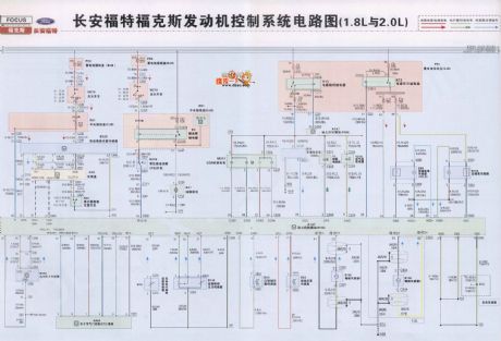
Ford Focus engine starting control system circuit
Published:2011/7/2 3:23:00 Author:John | Keyword: control system, engine
View full Circuit Diagram | Comments | Reading(1306)
Automatic dimming curtain circuit
Published:2011/7/2 4:23:00 Author:John | Keyword: Automatic dimming curtain

When the outdoor light enhances, the interior light also enhances and the photodiode resistance becomes smaller. Then the point A’s potential rises to drive the output potential to rise on KD28’s pin 3. Besides, the potential on pin 5 decreases to drive the motor M to transfer. Afterwards, the curtain slowly closes until the indoor light weakens. The resistance of D increases until it is large enough to drive the bridge to be balanced again. Conversely, when there is less light, the motor M rotates reversely to drive the curtain to slowly open. C1 and R6 operate with delay effect. This can make the control process undergo gradually, thus being able to avoid motor’s repeated starting because of the accidentally opened curtain from wind blowing.
(View)
View full Circuit Diagram | Comments | Reading(1643)
Hyundai Elantra light and dashboard circuit (not installed with on-board computer)
Published:2011/7/2 4:39:00 Author:John | Keyword: light, dashboard, on-board computer

View full Circuit Diagram | Comments | Reading(1191)
TV remote control 03 circuit
Published:2011/7/2 4:40:00 Author:John | Keyword: TV remote control

View full Circuit Diagram | Comments | Reading(727)
TV remote control 04 circuit
Published:2011/7/2 4:40:00 Author:John | Keyword: TV remote control

View full Circuit Diagram | Comments | Reading(584)
ST6210 battery charger circuit
Published:2011/7/2 2:50:00 Author:John | Keyword: battery charger

Currently, the environmentally nickel-metal hydride batteries will gradually replace nickel-cadmium batteries. Therefore, the compatible chargers for nickel cadmium and Ni-MH batteries are needed. In this case, common monitoring methods for nickel-cadmium batteries are no longer suitable for charging nickel-metal hydride batteries. The termination method for battery charger is based on detecting the curve inflection point of battery voltage. The detection for the turning point of nickel-metal hydride batteries is not only allows the compatibility for the charger of nickel-metal hydride batteries and nickel-cadmium batteries. The detection can also extend the service life of nickel-cadmium batteries. The compatible charger can use a 8-bit microcontroller (MCU, such as ST's ST6210) for being controled.
(View)
View full Circuit Diagram | Comments | Reading(1650)
Double-tube Flyback DC-DC Converter Circuit
Published:2011/6/24 1:27:00 Author:Michel | Keyword: Double-tube, Flyback, DC-DC , Converter Circuit
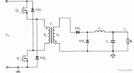
Double-tube flyback DC-DC converter circuit is shown as above.Among them,transformer,T1 acts as isolation,transmission,energy storge and 9 stores energy when switch tubes Q1 and Q2 turns on and Np releases energy to Ns,meanwhile,Np leakage feedbacks input signal via VD1 and VD2 and RCD leakage peak absorbing circuit can be saved when switch tubes Q1 and Q2 turns off.The low-pass filter composed of the inductor Lo and capacitance Co should be added to output port.In output loop,a rectifier diode VD3 is needed. (View)
View full Circuit Diagram | Comments | Reading(2258)
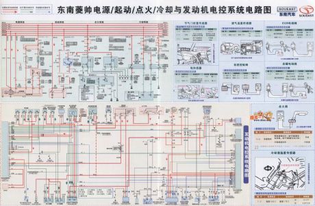
Southeast Lioncel power supply, starting, ignition, cooling system and engine control circuit
Published:2011/7/2 2:57:00 Author:John | Keyword: power supply, starting, ignition, cooling system, engine control
View full Circuit Diagram | Comments | Reading(707)
Silicon Controlled Capacitance Step-down LED Drive Circuit
Published:2011/7/1 8:25:00 Author:Michel | Keyword: Silicon Controlled , Capacitance Step-down, LED Drive Circuit

The above picture shows the silicon controlled capacitance step-down LED drive circuit.In this circuit, silicon controlled SCR and R3 constitute protection circuit, when the current flows through the LED more than the setting , SCR conducts certain Angle and the circuit's current are divided and it makes the LED work in stable condtion,which keep the LEDaway from high voltage damage.
Picture:Silicon Controlled Capacitance Step-down LED Drive Circuit (View)
View full Circuit Diagram | Comments | Reading(810)
Voltage-Sensitive Resistor Voltage Reduced Capacitance LED Driving Circuit
Published:2011/6/24 20:38:00 Author:Michel | Keyword: Voltage-Sensitive Resistor, Voltage Reduced Capacitance, LED Driving Circuit

he aboved picture is a pratical voltage-sensitive resistor voltage reduced capacitance LED driving circuit 9.The difference between circuit and most application circuit is that it connects voltage sensitive resistance (It also can be transient voltage suppression LED).This resistance(transient voltage suppression LED) can effectivly run over inrush current transient voltage on undervoltage sensing to protect LED and other transistors. moment(such as lightning, the start of a great power ).Transient voltage suppressor response time is commonly ns level. (View)
View full Circuit Diagram | Comments | Reading(1235)
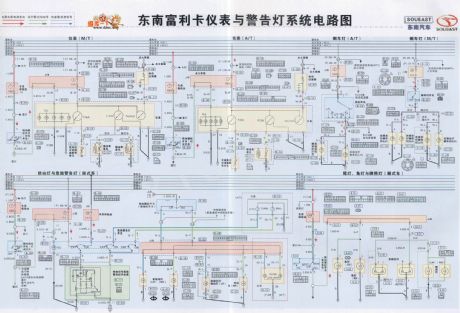
Southeast Freeca meter and warning light system circuit
Published:2011/7/2 3:21:00 Author:John | Keyword: meter, warning light system
View full Circuit Diagram | Comments | Reading(767)
combustible gas automatic ignition device circuit
Published:2011/7/2 3:37:00 Author:John | Keyword: combustible gas, automatic ignition device
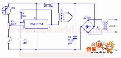
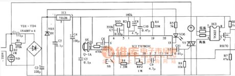
The device uses TWH8751 power electronic manifold to form a high voltage spark ignition device, which is made to be under the control of flame feedback optical signal. It also has the function to re-ignite after the turning off for some reason. If this device is compatible with other control circuit, the entire unit is able to achieve the automation of cooking. TWH8751, R1, C1 and others are used to constitute the square-wave generator. B2 is a booster, which can be the 12-inch ignition coil. Its primary stage uses 30 turns of 0.3mm enameled wire or output transformer in the tube radio with direct substitution.
(View)
View full Circuit Diagram | Comments | Reading(1095)
The Most Simple Capacitance Step-down Circuit
Published:2011/7/1 8:34:00 Author:Michel | Keyword: Most Simple, Capacitance Step-down, Circuit
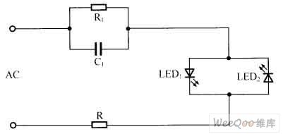
Shown as the picture,the two reverse parallel connection LED commute the step-down AC current.The circuit is widely used in luminous lamp, button lights and some position indicator light which have no high requirement.
Picture:The Most Simple Capacitance Step-down Circuit (View)
View full Circuit Diagram | Comments | Reading(613)
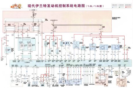
Hyundai Elantra engine control system circuit (1.6L, 1.8L model)
Published:2011/7/2 4:33:00 Author:John | Keyword: engine control system
View full Circuit Diagram | Comments | Reading(2533)
| Pages:1638/2234 At 2016211622162316241625162616271628162916301631163216331634163516361637163816391640Under 20 |
Circuit Categories
power supply circuit
Amplifier Circuit
Basic Circuit
LED and Light Circuit
Sensor Circuit
Signal Processing
Electrical Equipment Circuit
Control Circuit
Remote Control Circuit
A/D-D/A Converter Circuit
Audio Circuit
Measuring and Test Circuit
Communication Circuit
Computer-Related Circuit
555 Circuit
Automotive Circuit
Repairing Circuit