
Circuit Diagram
Index 1627
Earphone Amplifying Circuit of OPA2134
Published:2011/6/24 2:24:00 Author:Michel | Keyword: Earphone, Amplifying Circuit

The circuit is composed of OPA2134 and triodes etc. (View)
View full Circuit Diagram | Comments | Reading(4652)
Byd MOS Tube Supply
Published:2011/6/24 10:09:00 Author:Michel | Keyword: Byd, MOS Tube, Supply

Detailed Instructions of Byd MOS Tube Supply and Mosfet
Original:BF92N60,BF94N60,BF96N60,BF98N60,BF910N60,BF912N60
Properties and advantages: stable performance and preferential price
Product use: switching power supply, adapters, HID ballast
After-sales service: We provide technical support, and the original BYD signed agreement of the quality.
Packing: tubes (each tube 50 PCS), each box 5000 PCS. The package TO 220 (F)
Note: shenzhen Aisen science and technology is the agent of BYD series
MOS,namely,BF92N60,BF94N60,BF96N60,BF98N60,BF910N60,BF912N60 and we have stocks for long time and welcome to call Mr Zhao via13760184506.In addition,our company is the agent of BYD power management IC-BF1501,AC/AC.
Welcome to download and the information is from www.dzsc.com. (View)
View full Circuit Diagram | Comments | Reading(704)
the alarm circuit of water break in the spray pipe for seeding-machine(4)
Published:2011/6/29 7:13:00 Author:Ariel Wang | Keyword: alarm , water break , spray pipe , seeding-machine
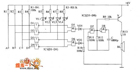
When the spray pipe is blocked,the output end of the not gate outputs high level.The output end becomes low level.The LED of the circuit is lighted.It indicates how many the blocked spray pipes are.At the same time,the audio oscillatory circuit works.BL gives out alarm sound.For example,the spray pipes in circuit A are blocked.Then there's no water in sprayer spraying out.The not gate D1 outputs low level.VL1 is lighted.The NAND gate D5 outputs high level.VD1 is conducted.The audio oscillator works.After the audio oscillatory signal is amplified by V,the driver BL gives out alarm sound. (View)
View full Circuit Diagram | Comments | Reading(476)
the alarm circuit of water break in the spray pipe for seeding-machine(3)
Published:2011/6/30 7:42:00 Author:Ariel Wang | Keyword: alarm , water break , spray pipe , seeding-machine
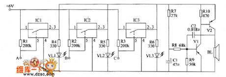
The water break detected circuit consists of switch integrated circuit IC1~IC3 and the resistor RI~R3。The ends of A~C are connected with water spray pipes of three circuits.When any water spray pipe is blocked,the pin-5 of the electronic switch integrated circuit becomes high level.The electronic switch inside is connected and conducted.The LED is lighted.It indicates how many the blocked water sprays are.At the same time,the audio oscillator circuit works.BL gives out alarm sound.For example,the water spray pipe in circuit A is blocked,there is no water spraying out from the sprayer.The electronic switch inside IC1 is conducted.VL1 is lighted.V1 and V2 are conducted to work.BL gives out the alarm sound.
(View)
View full Circuit Diagram | Comments | Reading(439)
Voice Filter Circuit of LM387
Published:2011/6/24 2:12:00 Author:Michel | Keyword: Voice, Filter Circuit

Serial Voice frequency range filter circuit is shown as above and its frequency range is 360Hz-3KHz. (View)
View full Circuit Diagram | Comments | Reading(1239)
RS-232 serial interface circuit designed with two transistors
Published:2011/7/1 7:03:00 Author:Fiona | Keyword: serial interface, designed with two transistors


The above is the MAX232's internal circuit.
The below that I make is the 6688 data line circuit which uses transistor, capacitor C7 produces negative pressure:
(View)
View full Circuit Diagram | Comments | Reading(2308)
Complementary tube double bistable circuit
Published:2011/6/30 8:09:00 Author:Fiona | Keyword: Complementary tube, double bistable


Complementary tube double bistable circuit is shown in Figure 1 (a).When it is charged tothe power supply,if there is no trigger effect,because the collector current is very small and the voltage of Rc1 and Rc2 is also small,two tubes are both off,the circuit keeps the steady state.Under the trigger pulse,assume BG1 changes from close to enlarge,and produces following the avalanche of positive feedback process.Quickly make the two tubes be saturate connected,in another steady state,capacitance C1 is accelerated capacitance,by the form 1(b) visible,uc1 is steeply down to zero,but UC2 is steeply from zero up to Ec.
(View)
View full Circuit Diagram | Comments | Reading(862)
the alarm circuit of the blocked seed channel in seeding-machine (2)
Published:2011/7/1 17:41:00 Author:Ariel Wang | Keyword: alarm , blocked , seed channel , seeding-machine
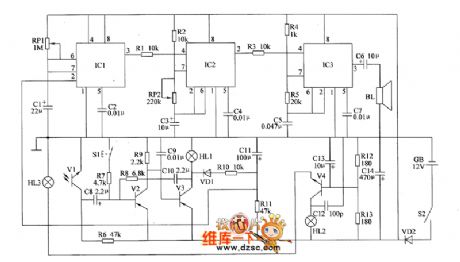
The photoelectric sensor consists of HL3 and V1.It used to detect if there are seeds in the seed channel.When seeding,the seed passes through the optical path of the photoelectric sensor constantly.It breaks the optical path between HL3 and V1.The internal resistance is large.At this time,V2 is saturated to conduct.V3 is stopped.HL1 is not lighted.The pin-3 of IC1 outputs low level.The 1Hz multivibrator and 1kHz multivibrator are not working.B1 doesn't give a sound.When the seed channel is blocked or there are no seeds,the light of HL3 shines on V1.V1 is with the low resistivity.V2 is stopped.V3 is conducted.HL1 is lighted.
(View)
View full Circuit Diagram | Comments | Reading(543)
LED(relay) drive circuit diagram
Published:2011/6/30 13:45:00 Author:Sophia | Keyword: LED(relay), drive circuit

(View)
View full Circuit Diagram | Comments | Reading(723)
LA7846N-Vertical scanning output thick-film integrated circuit
Published:2011/6/30 15:45:00 Author:leo | Keyword: LA7846N-Vertical scanning output thick-film integrated circuit

LA7846N is vertical scanning output thick-film integrated circuit which is widely used in big screen color television.
Function features:The integrated circuit LA7846N contains field deflection urging circuit, field deflection power amplifier circuit, pump power supply circuit, protecting circuit and other related circuits.
Pin functions and data:The integrated circuit LA7846N uses 10 pin single line package. Pin functions and data are shown in the picture. (View)
View full Circuit Diagram | Comments | Reading(790)
Optical receiver circuit diagram
Published:2011/7/2 21:18:00 Author:leo | Keyword: Optical receiver circuit diagram, LA7224

The picture shows a optical receiver circuit. In this circuit, LA7224 is a kind of front amplifier which is used to receive signals. Peak value keeping circuit, integral circuit and so on can form the integrated circuit of the same chip. The syntony circuit formed by L and G2 are used to get carrier and the carrier comes through the amplitude-limited circuit to keep the peak value (C3), by which the S/N of this circuit is improved. C4 is integral circuit and capacitor recommended is 0.0047μF. When the output voltage of the pin 1 of LA7224 is 0.3 V, VT1 is stopped and output voltage is U which is a high value. (View)
View full Circuit Diagram | Comments | Reading(867)
LA7845N-Field scanning output integrated circuit
Published:2011/7/2 21:27:00 Author:leo | Keyword: LA7845N-Field scanning output integrated circuit

LA7845N is a kind of field scanning output integrated circuit made by Sanyo corporation which is widely used in big screen color television.
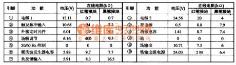
It has few peripheral components and adopts negative sources to offer the power. It does not perfect over current, overvoltage and overheating protecting circuit. Besides, the maximum output current of it is 3Ap-p and the maximum power consumption is 11W while the maximum output voltage is 40 V. The maximum source output voltage can reach 85 V. The inner circuit of this integrated circuit is shown in the picture and you can also find the pin functions and related data in it. (View)
View full Circuit Diagram | Comments | Reading(673)
LA7840, LA7841, LA7845 and LA7846-Field scanning output integrated circuit
Published:2011/7/3 2:09:00 Author:leo | Keyword: LA7840, LA7841, LA7845 and LA7846-Field scanning output integrated circuit

LA7840, LA7841, LA7845 and LA7846 are a kind of field scanning output integrated circuit made by Sanyo Corporation in Japan. They are widely used in color television with different screens.
1.Function features:
They have vertical output circuit, over current protecting circuit and use DC differential input method. The maximum output current of LA7840 is 1.8Ap-p and the maximum output power is 9W. The maximum output current of LA7841 is 2.2Ap-p and the maximum output power is 9W. The maximum output current of LA7845 is 2.2Ap-p and the maximum output power is 11W. The maximum output current of LA7846 is 3Ap-p and the maximum output power is 20W.
2.in functions and related data:
All information about their pin functions and related data are shown in the picture.
(View)
View full Circuit Diagram | Comments | Reading(4864)
LA7838-Field scanning output integrated circuit
Published:2011/7/3 2:16:00 Author:leo | Keyword: LA7838-Field scanning output integrated circuit
LA7838 is a type of field scanning output integrated circuit made by Sanyo Cooperation in Japan. It is widely used in color television.
1.Function features:
The integrated circuit LA7838 contains saw tooth generator circuit, field scanning output circuit, and other related circuits.
2.The integrated circuit LA7838 adopts 13 pin single line packages. The related information is all shown in the picture.
Reminder: LA7838 the reducing output capability of the capacitor pin 12 will cause retrace line shows in the screen. (View)
View full Circuit Diagram | Comments | Reading(521)
TMP87CS38N-XXXX-Projection VT dedicated single chip microcomputer integrated circuit
Published:2011/7/3 2:52:00 Author:leo | Keyword: TMP87CS38N-XXXX-Projection VT dedicated single chip microcomputer integrated circuit

(View)
View full Circuit Diagram | Comments | Reading(723)
555 adjustable speed electric toy car circuit
Published:2011/6/12 7:39:00 Author:nelly | Keyword: electric toy car
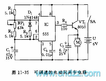
The astable multivibrator is composed of 555 and R1, R2, R3, RP1 and C1. When it is connected to power supply, because C1's voltage can not suddenly change, 555 is in set state by 2 foot's low level, VT1 is turned on by 3 foot's high level, the motor obtains electricity and runs. When C1 is charged to 2/3 VDD(4V) by R1, RP1, R2, 555 is turned and reset, 3 foot turns to low level, VT1 cuts off, the motor M is no electricity, the electric motor car slides depends on the inertial property. At this time, C1's electricity is discharged to the chip internal diacharge lamp by R3, D1, namely, the discharge circuit and charge circuit is separated due to D1's connection, and because the resistance value of RP1+R2 is larger than R3, so the discharge is done in R3.
(View)
View full Circuit Diagram | Comments | Reading(2571)
Circuit: Samsung CE959 microwave _ page _2
Published:2011/6/27 21:13:00 Author:zj | Keyword: Samsung CE959 microwave, page _2

View full Circuit Diagram | Comments | Reading(645)
555 simplified double wires logical state judge circuit
Published:2011/6/12 9:22:00 Author:nelly | Keyword: simplified double wires, logical state
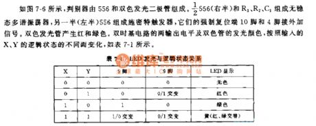
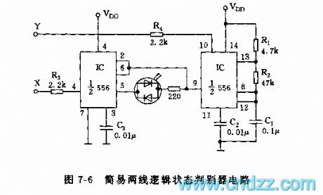
As shown on the figure 7-6, the judger consists of the 556 anddouble-color LED. The actable multivibrator consists of the the right side of 556 and R1,R2,C1. The left side of 556 makes up of the Schmitt trigger. Their 10 foot and 4 foot contact external signal. The double-color LED produces red and green light. The dual time base circuit's output level and the double color CRT's color-emitting change with the logical state of the X and Y.
(View)
View full Circuit Diagram | Comments | Reading(781)
555 ultrasonic liquid level indicator circuit
Published:2011/6/12 8:59:00 Author:nelly | Keyword: ultrasonic, liquid level
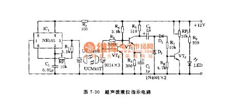
As shown on the figure 7-30, this circuit consists of the ultrasonic transmitting circuit and receiving circuit. Its hydraulic measurement is better than others, because the measured liquid's concentration and conductivity don't have effects on its ultrasonic. The ultrasonic transmitting circuitconsists of the 555,R1,RP1,C1 and ultrasonic generation. The receiving circuit consists of VT1,VT2 and detection circuit. If the liquid level is more close to the receiver sensor, the angle of the voltmeter will be bigger.
(View)
View full Circuit Diagram | Comments | Reading(1537)
TMP87CS38N-Single chip microcomputer integrated circuit
Published:2011/7/3 3:08:00 Author:leo | Keyword: TMP87CS38N-Single chip microcomputer integrated circuit

TMP87CS38N is a kind of single chip microcomputer integrated circuit made by Toshiba in Japan. It is especially used in the microcontroller chip of changhong projection color television 51PT28A.
1.Function features:The integrated circuit TMP87CS38N, memory AT25C08, IR-Control emitter K8G, IR-Control signal receiver HSO038 as well as interface circuits form complete color television remote control circuit. Except the various control functions, it has +148 V, +18 V and -18 V power supply over current test and protection function.
2.Pin functions and related data:The integrated circuit TMP87CS38N adopts 42 pin dual line package. All information is shown in the picture. (View)
View full Circuit Diagram | Comments | Reading(636)
| Pages:1627/2234 At 2016211622162316241625162616271628162916301631163216331634163516361637163816391640Under 20 |
Circuit Categories
power supply circuit
Amplifier Circuit
Basic Circuit
LED and Light Circuit
Sensor Circuit
Signal Processing
Electrical Equipment Circuit
Control Circuit
Remote Control Circuit
A/D-D/A Converter Circuit
Audio Circuit
Measuring and Test Circuit
Communication Circuit
Computer-Related Circuit
555 Circuit
Automotive Circuit
Repairing Circuit