555 Circuit
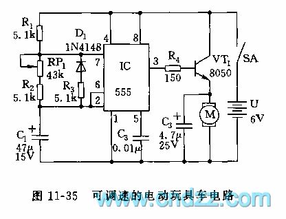
555 adjustable speed electric toy car circuit
Published:2011/6/12 7:39:00 Author:nelly | Keyword: electric toy car | From:SeekIC

The astable multivibrator is composed of 555 and R1, R2, R3, RP1 and C1. When it is connected to power supply, because C1's voltage can not suddenly change, 555 is in set state by 2 foot's low level, VT1 is turned on by 3 foot's high level, the motor obtains electricity and runs. When C1 is charged to 2/3 VDD(4V) by R1, RP1, R2, 555 is turned and reset, 3 foot turns to low level, VT1 cuts off, the motor M is no electricity, the electric motor car slides depends on the inertial property. At this time, C1's electricity is discharged to the chip internal diacharge lamp by R3, D1, namely, the discharge circuit and charge circuit is separated due to D1's connection, and because the resistance value of RP1+R2 is larger than R3, so the discharge is done in R3.
Reprinted Url Of This Article:
http://www.seekic.com/circuit_diagram/555_Circuit/555_adjustable_speed_electric_toy_car_circuit.html
Print this Page | Comments | Reading(3)

Article Categories
power supply circuit
Amplifier Circuit
Basic Circuit
LED and Light Circuit
Sensor Circuit
Signal Processing
Electrical Equipment Circuit
Control Circuit
Remote Control Circuit
A/D-D/A Converter Circuit
Audio Circuit
Measuring and Test Circuit
Communication Circuit
Computer-Related Circuit
555 Circuit
Automotive Circuit
Repairing Circuit
Code: