
Circuit Diagram
Index 1641
The ceiling lamp control switch circuit (2)
Published:2011/7/3 6:43:00 Author:Borg | Keyword: ceiling lamp, control switch
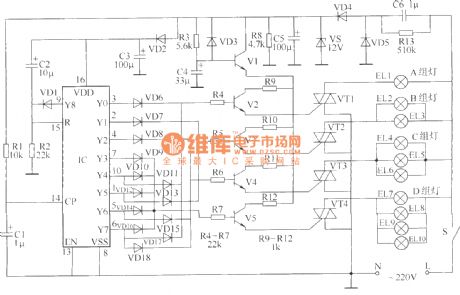
The circuit control switch that is going to be introduced here can be used to control the ceiling lamps(or fancy lamps), and it can make the ceiling lamps indicate 8 lighting states by controlling the closing times of the switches of former lights. The circuit consists of the power supply, counting/pulse distributor and the control circuit, see as the figure.
Element selection All of R1~R12 are made of the 1/4W or 1/8W carbon film resistor; R13 is the 1/2W carbon resistor. All of C1~C5 are the the aluminum electrolytic resistors whose withstand voltages are 16V. (View)
View full Circuit Diagram | Comments | Reading(646)
The infrared remote control switch circuit of ceiling lamps
Published:2011/7/3 6:55:00 Author:Borg | Keyword: infrared, remote control, ceiling lamps
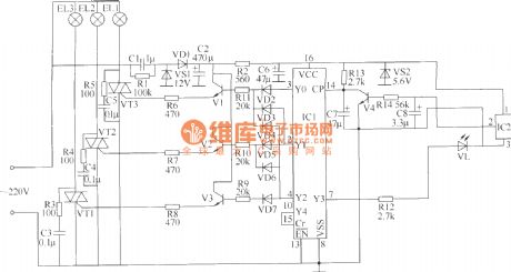
The infrared remote control switch circuit of ceiling lamps which is to be introduced here can be used in the remote controls of domestic electric apparatus(such as TV sets, disc players and videos, etc) to turn on/off the lamps or choose the brightness of the lamps. By pressing a random key on the remote control continuously, the lights of first team are lighting, both the 1st and 2nd teams of light are ON, all the lights of 3 teams are glowing, all the lights of 3 lines are OFF, and the lamps in 1st team are lighting```the lights change in this order.The circuit consists of the power supply circuit, infrared reception circuit, counting/distributor and the control executing circuit.
(View)
View full Circuit Diagram | Comments | Reading(782)
The electric over-voltage relay circuit
Published:2011/7/3 7:31:00 Author:Borg | Keyword: over-voltage relay
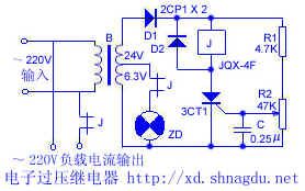
The electric over-voltage relay circuit The circuit is simple, when the power supply voltage is over the limit value, it will take action, the power supply is cut off, which makes sure the load won't be two high. The power supply of the relay and the controllable silicon is turned into 24V by the transformer, and then rectified by D1, the relay and the controllable silicon are connected together in the parallel way. R1 and R2 are the distributing resistors, the control pole LEV can be controlled by adjusting R2, so the SCR can be conducting in the selected voltage. When the power supply voltage reaches the limit value of the SCR, the SCR is conducting.
(View)
View full Circuit Diagram | Comments | Reading(1050)
The anti-parallel or bridge SCR trigger circuit
Published:2011/7/3 7:41:00 Author:Borg | Keyword: anti-parallel, bridge, SCR trigger
View full Circuit Diagram | Comments | Reading(2316)
The multi-function time delay switch power supply outlet
Published:2011/7/3 20:16:00 Author:Borg | Keyword: multi-function, time delay switch, power supply

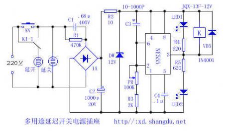
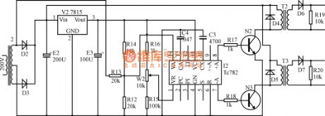
Turning on or off of domestic electric apparatus and lighting lamp is often done after some delayed time, this power supply outlet can meet these needs.Working principle: see as the figure, the circuit consists of the step-down, rectifier, filter and time delay control circuit and other parts.
By pressing AN, the 12V voltage is imposed on the delayer, at the moment, the 2-pin and 6-pin of NE555 are in a high LEV, and 3-pin of NE555 is outputting a low LEV, so relay K gets power, the contactor K1-1 is pulling in upward, and the delay shut outlet is getting power. (View)
View full Circuit Diagram | Comments | Reading(1719)
The single tube time delay pulling in relay circuit
Published:2011/7/3 20:17:00 Author:Borg | Keyword: single tube, time delay, relay circuit
View full Circuit Diagram | Comments | Reading(629)
The single key touch switch circuit
Published:2011/7/3 20:30:00 Author:Borg | Keyword: single key, touch switch
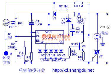
Here is to introduce a single key touch switch circuit composed of CD4017, this circuit is controlled by single touch on the pole, every time it is touched, the switch will take action(ON/OFF) once, whose functions are the same with ordinary switch, and it is convenient to use.The working principle is shown in the figure, of which HD is the neon bulb of tube type, it consists of the self-made photoelectric coupler with resistor RG, and it forms the touching signal input circuit with the touch poles of M and R1. The odd input terminals Q1, Q3,Q5, Q7 and 9Q, etc, of CD4017 are connected with diodes of V2~V6, respectively.
(View)
View full Circuit Diagram | Comments | Reading(1789)
The single tube time delay releasing relay circuit
Published:2011/7/3 20:19:00 Author:Borg | Keyword: single tube, time delay
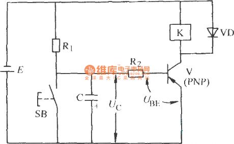
In Figure a) is the PNP tube time delay releasing circuit
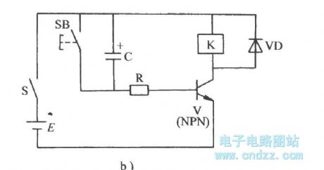
In Figure a) is theNPN tube time delay releasing circuit (View)
View full Circuit Diagram | Comments | Reading(878)
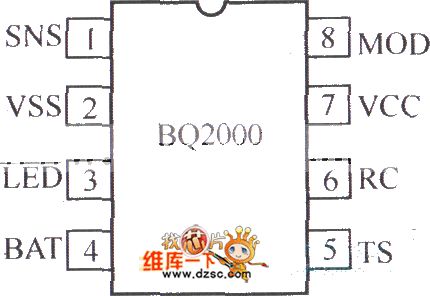
Charger circuit composed of the BQ2000
Published:2011/7/1 0:52:00 Author:TaoXi | Keyword: Charger circuit

View full Circuit Diagram | Comments | Reading(1632)
Conversion amplifier circuit
Published:2011/7/1 0:54:00 Author:TaoXi | Keyword: Conversion, amplifier

The Conversion amplifier circuit is as shown in figure:
(View)
View full Circuit Diagram | Comments | Reading(495)
LA3160 audio IC circuit
Published:2011/7/1 0:55:00 Author:TaoXi | Keyword: audio IC

The LA3160 audio IC circuit is as shown in the figure:
(View)
View full Circuit Diagram | Comments | Reading(2677)
Charging circuit composed of the LP3945
Published:2011/7/1 0:56:00 Author:TaoXi | Keyword: Charging circuit

View full Circuit Diagram | Comments | Reading(509)
BQ2000 charging controller circuit
Published:2011/7/1 0:58:00 Author:TaoXi | Keyword: charging controller
View full Circuit Diagram | Comments | Reading(553)
LA3161 audio IC circuit
Published:2011/7/1 0:58:00 Author:TaoXi | Keyword: audio IC

The LA3161 audio IC circuit is as shown in the figure:
(View)
View full Circuit Diagram | Comments | Reading(3933)
Programmable amplifier circuit with the high-speed gain
Published:2011/7/1 1:00:00 Author:TaoXi | Keyword: Programmable amplifier, high-speed gain

The Programmable amplifier circuit with the high-speed gain is as shown in the figure:
(View)
View full Circuit Diagram | Comments | Reading(613)
Current inductive circuit composed of the LP3945
Published:2011/7/1 1:03:00 Author:TaoXi | Keyword: Current inductive

View full Circuit Diagram | Comments | Reading(434)
LA3210 audio IC circuit
Published:2011/7/1 1:04:00 Author:TaoXi | Keyword: audio IC

The LA3210 audio IC circuit is as shown in the figure:
(View)
View full Circuit Diagram | Comments | Reading(2082)
Practical adjustable ratio differential amplifier circuit
Published:2011/7/1 1:05:00 Author:TaoXi | Keyword: Practical, adjustable ratio, differential amplifier

The Practical adjustable ratio differential amplifier circuit is as shown in the figure:
(View)
View full Circuit Diagram | Comments | Reading(608)
LA3220 audio IC circuit
Published:2011/7/1 1:06:00 Author:TaoXi | Keyword: audio IC

The LA3220 audio IC circuit is as shown in the figure:
(View)
View full Circuit Diagram | Comments | Reading(3087)
High performance logic command control gain amplifier circuit
Published:2011/7/1 1:08:00 Author:TaoXi | Keyword: High performance, logic command control, gain, amplifier

The High performance logic command control gain amplifier circuit is as shown in the figure:
(View)
View full Circuit Diagram | Comments | Reading(512)
| Pages:1641/2234 At 2016411642164316441645164616471648164916501651165216531654165516561657165816591660Under 20 |
Circuit Categories
power supply circuit
Amplifier Circuit
Basic Circuit
LED and Light Circuit
Sensor Circuit
Signal Processing
Electrical Equipment Circuit
Control Circuit
Remote Control Circuit
A/D-D/A Converter Circuit
Audio Circuit
Measuring and Test Circuit
Communication Circuit
Computer-Related Circuit
555 Circuit
Automotive Circuit
Repairing Circuit