
Circuit Diagram
Index 1656
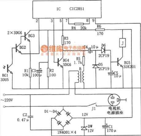
energy saving remote shutdown control of television circuit(CIC2851)
Published:2011/6/23 19:58:00 Author:chopper | Keyword: energy saving, remote shutdown control, television circuit
View full Circuit Diagram | Comments | Reading(365)
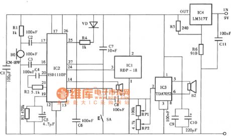
telequipment of water level of cistern wired telemetry circuit
Published:2011/6/23 20:01:00 Author:chopper | Keyword: wired telemetry, water level, cistern, telequipment

View full Circuit Diagram | Comments | Reading(1377)
audio power amplifier (OPA604) circuit of high-performance but samll power
Published:2011/6/29 0:32:00 Author:chopper | Keyword: audio power amplifier, high-performance, samll power

The picture is a audio power amplifition circuit of high-performance but samll power.The preceding stage of circuit adopts FET hi-fi op-amp OPA604,and the backward stage adopts high-speed buffer BUF634, and the voltage will cascade negative feedback between the dual-stage amplifier.The volatge amplifition time is detemined by two resistors(5kΩ and 250Ω) of feedback branch,and their values are 1+5kΩ/250Ω≈21 times.BUF634 is high-speed buffer.The internal structure simplified circuit is shown as picture (b).
(View)
View full Circuit Diagram | Comments | Reading(1094)
LM386 universal audio power amplifier circuit
Published:2011/6/29 0:38:00 Author:chopper | Keyword: universal, audio power amplifier

The picture is a universal audio power amplifier circuit.The picture (a) shows the principle,and this circuit adopts integrated power amplifier LM386.This element is a universal power amplifier and it is cheap.The picture (c) shows the inner structure of LM386.
(View)
View full Circuit Diagram | Comments | Reading(1676)
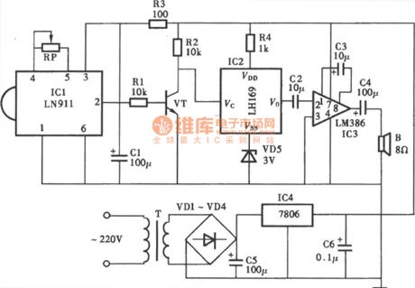
Electronic guard dog circuit
Published:2011/6/28 21:50:00 Author:chopper | Keyword: Electronic, guard dog
View full Circuit Diagram | Comments | Reading(617)
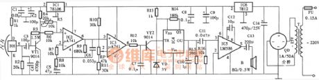
2W audio power amplifier circuit of LM380
Published:2011/6/29 0:55:00 Author:chopper | Keyword: 2W, audio power amplifier

The picture is a 2W audio power amplifier circuit.This circuit adopts 14 pinned LM380 as the amplifier.Add the input signal to the inverting input end(pin 6) of operational amplifier LM380 through the volume control potentiometer Rp(20kΩ) and 22μF coupling capacitor and its in - phase input end (pin 2) is used to earth,pin 1 is circumscribed with 10μF filter capacitor to eliminate the high frequency ripple interference.The circuit adopts 16V single power supply,and circumscribes a 470μF decoupling capacitor between supply end(pin 14) and ground.Between the output end(pin 8) and ground there are two parallel branches.
(View)
View full Circuit Diagram | Comments | Reading(2717)
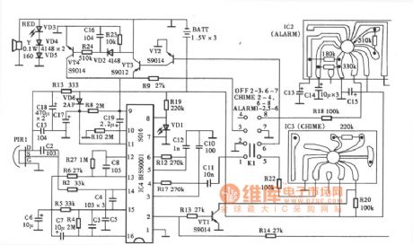
alarm system of cultural relics circuit
Published:2011/6/29 0:39:00 Author:chopper | Keyword: alarm system, cultural relics
View full Circuit Diagram | Comments | Reading(493)
SNS-200P1R pyroelectric infrared alarm
Published:2011/6/29 0:56:00 Author:chopper | Keyword: pyroelectric, infrared alarm
View full Circuit Diagram | Comments | Reading(449)
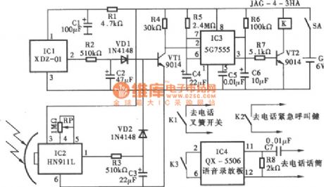
Security alarm telephone system circuit
Published:2011/6/29 0:57:00 Author:chopper | Keyword: Security alarm, telephone system
View full Circuit Diagram | Comments | Reading(482)
electric shock alarm circuit(3)
Published:2011/6/29 0:58:00 Author:chopper | Keyword: electric shock, alarm
View full Circuit Diagram | Comments | Reading(712)
electric shock alarm circuit(2)
Published:2011/6/29 0:59:00 Author:chopper | Keyword: electric shock, alarm
View full Circuit Diagram | Comments | Reading(1155)
electric shock alarm circuit(1)
Published:2011/6/29 0:59:00 Author:chopper | Keyword: electric, shock alarm

View full Circuit Diagram | Comments | Reading(1222)
The high-power dual-way controllable dimmer circuit triggered by Ne lamps
Published:2011/6/29 4:52:00 Author:Seven | Keyword: high-power, dual-way, controllable dimmer
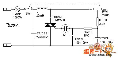
The high-power dual-way controllable dimmer circuit triggered by Ne lamps
(View)
View full Circuit Diagram | Comments | Reading(1536)
The classical power supply (7805 current expanding) circuit
Published:2011/6/29 4:55:00 Author:Seven | Keyword: power supply, current expanding

View full Circuit Diagram | Comments | Reading(1797)
The comparison of several VI converter and constant current circuits
Published:2011/6/29 4:58:00 Author:Seven | Keyword: VI converter, constant current circuits

View full Circuit Diagram | Comments | Reading(1274)
The stepless dimmer circuit of special integrated circuits
Published:2011/6/29 0:57:00 Author:Seven | Keyword: stepless dimmer, integrated circuits

The figured circuit is the key control stepless dimmer circuit composed of HT7700A dimming special integrated circuit, which is controlled by a SB single key, and the dimming brightness has 96 stages.
(View)
View full Circuit Diagram | Comments | Reading(671)
The TXDl742 continuous adjusted full-automation AC regulator circuit
Published:2011/6/29 6:18:00 Author:Seven | Keyword: full-automation, AC regulator circuit

View full Circuit Diagram | Comments | Reading(610)
The auto controller circuit of toilet lights and ventilators
Published:2011/6/29 6:12:00 Author:Seven | Keyword: auto controller circuit, toilet lights
Working principles The working principles is shown in the figure, which consists of the magnet switch circuit, single steady time delay circuit, light lamp control circuit, ventilator control circuit and power supply circuit, etc. When the toilet is closed, the permanent magnet ZT is near the normally closed reed pipe AG, due to the magnet effect of ZT, the internal touch chip of AC is broken down, and the triode VT is blocked without the bias current, at the moment, the time-based integrated circuit IC1 2-pin is in a high LEV, so IC1 is in a reset state, and 3-pin if IC1 is outputting a low LEV.
(View)
View full Circuit Diagram | Comments | Reading(703)
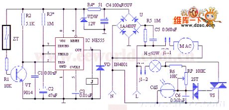
Electric sewing machine no-load economizer circuit diagram 1
Published:2011/6/13 5:12:00 Author:Lucas | Keyword: Electric , sewing machine, no-load , economizer
The electric sewing machine no-load economizer circuit is composed of the DC regulated power supply circuit, sensor control circuit and the main control circuit, and the circuit is shown as the chart. The DC regulated power supply circuit consists of step-down capacitor C1, drain resistor R1, bridge rectifier UR, filter capacitors C2 and C3, current limiting resistor R2 and Zener diode VS. Sensor control circuit is composed of the magnet and Hall sensor IC IC which are installed in the clutch lever of sewing machine (it includes the Hall element, differential amplifier, Schmitt trigger, and output circuit), resistors R3 and M, the capacitor C4, transistor V, diode VD, LED VL and relay K.
(View)
View full Circuit Diagram | Comments | Reading(1337)
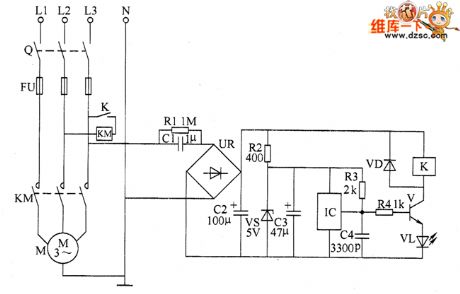
Motor underloading energy saver circuit diagram 2
Published:2011/6/13 6:04:00 Author:Lucas | Keyword: Motor, underloading, energy saver
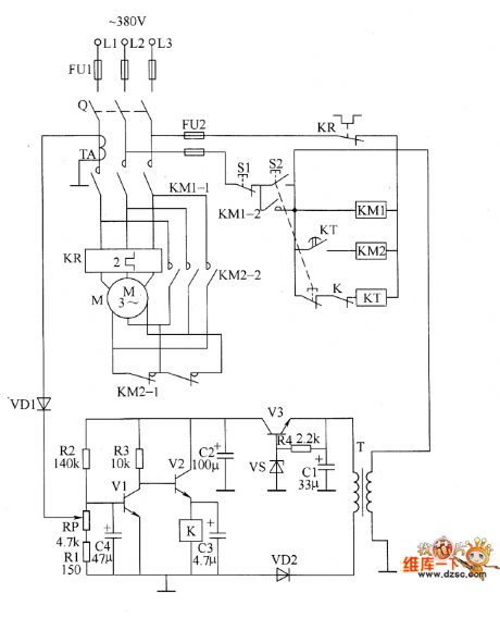
The motor underloading energy saver circuit is composed of the power supply circuit, power transformer T, voltage adjustment tube V3, voltage regulator diode VS, rectifier diode VD2, resistor R4 and filter capacitors C1 and C2 and so on. Current sampling detection circuit is composed of the current transformer TA, diode VD1, potentiometer RP, resistors R1 and R2, capacitor C4 and so on. Control circuit consists of the power switch Q, stop button S1, start button S2, transistors V1 and V2, relay K, time relay KT, AC contactors KM1 and KM2 and so on. R1 ~ R4 select 1/4W carbon film resistors. RP uses small potentiometer or variable resistor. C1 uses aluminium electrolytic capacitors with the voltage in 50V.
(View)
View full Circuit Diagram | Comments | Reading(1522)
| Pages:1656/2234 At 2016411642164316441645164616471648164916501651165216531654165516561657165816591660Under 20 |
Circuit Categories
power supply circuit
Amplifier Circuit
Basic Circuit
LED and Light Circuit
Sensor Circuit
Signal Processing
Electrical Equipment Circuit
Control Circuit
Remote Control Circuit
A/D-D/A Converter Circuit
Audio Circuit
Measuring and Test Circuit
Communication Circuit
Computer-Related Circuit
555 Circuit
Automotive Circuit
Repairing Circuit