Basic Circuit
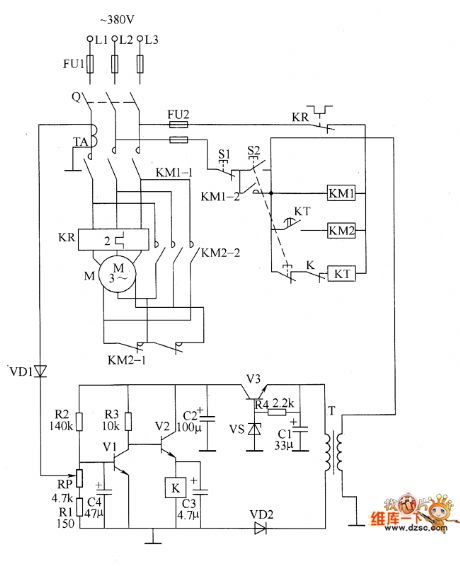
Motor underloading energy saver circuit diagram 2
Published:2011/6/13 6:04:00 Author:Lucas | Keyword: Motor, underloading, energy saver | From:SeekIC

The motor underloading energy saver circuit is composed of the power supply circuit, power transformer T, voltage adjustment tube V3, voltage regulator diode VS, rectifier diode VD2, resistor R4 and filter capacitors C1 and C2 and so on. Current sampling detection circuit is composed of the current transformer TA, diode VD1, potentiometer RP, resistors R1 and R2, capacitor C4 and so on. Control circuit consists of the power switch Q, stop button S1, start button S2, transistors V1 and V2, relay K, time relay KT, AC contactors KM1 and KM2 and so on. R1 ~ R4 select 1/4W carbon film resistors. RP uses small potentiometer or variable resistor. C1 uses aluminium electrolytic capacitors with the voltage in 50V.
Reprinted Url Of This Article:
http://www.seekic.com/circuit_diagram/Basic_Circuit/Motor_underloading_energy_saver_circuit_diagram_2.html
Print this Page | Comments | Reading(3)

Article Categories
power supply circuit
Amplifier Circuit
Basic Circuit
LED and Light Circuit
Sensor Circuit
Signal Processing
Electrical Equipment Circuit
Control Circuit
Remote Control Circuit
A/D-D/A Converter Circuit
Audio Circuit
Measuring and Test Circuit
Communication Circuit
Computer-Related Circuit
555 Circuit
Automotive Circuit
Repairing Circuit
Code: