
Circuit Diagram
Index 1643
audio firing key amplifition circuit formed by program-controlled op-amp F346
Published:2011/6/30 23:47:00 Author:chopper | Keyword: audio, firing key, amplifition, program-controlled, op-amp

This is a audio firing key amplifition circuit formed by four program-controlled integrated operational amplifier F346.The constant-current source circuit of program-controlled operational amplifier can be controlled by external part,and when constant flow source is loaded to the current bias,the op-amp will be in functional mode,or it will be on cutoff state.Additionally, when the value of current bias is changed,the parameter of the op-amp will be changed,too. (View)
View full Circuit Diagram | Comments | Reading(700)
electric fan infrared emitter (4011) circuit
Published:2011/6/30 7:00:00 Author:chopper | Keyword: electric fan, infrared emitter circuit
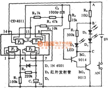
View full Circuit Diagram | Comments | Reading(1849)
TA8149N recording,playback preamplification integrated circuit
Published:2011/6/30 2:48:00 Author:chopper | Keyword: recording, playback, preamplification, integrated circuit


TA8149N is a recording,playback preamplification integrated circuit produced by Company TOSHIBA and used in double card machine,it is applied to the homemade and import music center widely.1.inner circuit and function of pins TA8149N integrated package includes two recording,playback preamplification circuits of same functions,metal tape/normal tape electronic switching convertion circuit,card A and card B electronic switching convertion circuit,ALC control circuit,power supply and bias voltage circuit.The inner circuit and typical application circuit are shown as picture 1.This IC adopts dual inline 24 pinned package,the functions of pins are shown as chart 1.
(View)
View full Circuit Diagram | Comments | Reading(1117)
preamplifier(OPA37) circuit of NAB magnetic head
Published:2011/6/30 2:33:00 Author:chopper | Keyword: preamplifier, NAB magnetic head

The picture is a preamplifier circuit of NAB magnetic head.This circuit adopts the magnetic head preamplifier formed by ultra-low noise and precise operational amplifier OPA37.This circuit can offer the standard NAB equal.When the frequency is 1kHz,the voltage amplifition time is 50db.The audio input signal is picked by magnetic head device and it is loaded to in-phase input end of OPA37.This connection method can make the operational amplifier possess high input impedance,that is to say,thepath between pin 3 of OPA37 and ground can be taken as a open circuit approximatively.The load impedance of magnetic head is formed by RL,CL and its resistance and capacity can be determined by the features of magnetic head device. (View)
View full Circuit Diagram | Comments | Reading(3073)
infrared emitter(MT8803) of electric fan circuit
Published:2011/6/30 2:20:00 Author:chopper | Keyword: infrared emitter, electric fan

View full Circuit Diagram | Comments | Reading(608)
low noise and hifi RIA preamplifier (OPA606) circuit
Published:2011/6/30 2:19:00 Author:chopper | Keyword: low noise, hifi, RIA, preamplifier

(View)
View full Circuit Diagram | Comments | Reading(953)
TA8126 DC/DC conversion integrated circuit
Published:2011/6/30 2:01:00 Author:chopper | Keyword: DC/DC, conversion, integrated circuit


TA8126 is a DC conversion integrated circuit,and it is applied to digital tuned radio systems to provide tuned selective calling circuit with tuned voltage by promoting the DC 3V voltage to 15V around tuned voltage.TA8126 has two encapsulation methods and we can distinguish them by different suffix letters.And TA81265 adopts single inline 9 pinned package;TA8126F adopts dual inline 10 pinned package.1.inner circuit and function of pins The inner circuit of TA8126F integrated package is shown as picture 1,and the function and data of pins of its integrated circuit are shown as chart 1.
(View)
View full Circuit Diagram | Comments | Reading(1099)
OPA502 hifi music center amplifition circuit
Published:2011/6/30 2:19:00 Author:chopper | Keyword: hifi, music center, amplifition circuit


The picture is a hifi music center amplifition circuit.This circuit adopts low noise precise op-amp OPA27 as a preamplifier.The greatest output power can reach 150W.When the output power is 50W and frequency is 20KHz,its total harmonic distortion is 0.02%.And when the frequency is 1KHz,the total harmonic distortion is 0.002%.OPA27 can improve its input impedance by using in-phase input method.When supply voltage is ±15V,the dynamic range of linearity is ±12V.
(View)
View full Circuit Diagram | Comments | Reading(896)
ultrasonic remote control jacklight circuit
Published:2011/6/30 1:37:00 Author:chopper | Keyword: ultrasonic, remote control, jacklight circuit

View full Circuit Diagram | Comments | Reading(583)
ultrasonic blind - walking device circuit
Published:2011/6/30 1:36:00 Author:chopper | Keyword: ultrasonic, blind - walking device

View full Circuit Diagram | Comments | Reading(728)
ultrasonic eyes protector cirucit
Published:2011/6/30 1:14:00 Author:chopper | Keyword: ultrasonic, eyes protector

View full Circuit Diagram | Comments | Reading(502)
The temperature over-limit auto regulating outlet circuit
Published:2011/6/30 22:34:00 Author:qqtang | Keyword: temperature over-limit, auto regulating outlet

The figured circuit consists of the temperature detection switch, relay control circuit, language circuit, audio power amplifier circuit and AC step-down rectifier circuit, etc. When the temperature of the object or machine is over the set value, the outlet XS gets power and the ventilating or cooling device connected with the outlet is running. At the same time, the sound circuit is triggered and making sound, reminding people of the temperature change.
(View)
View full Circuit Diagram | Comments | Reading(1013)
The cool shutoff temperature control circuit
Published:2011/6/30 22:51:00 Author:qqtang | Keyword: temperature control
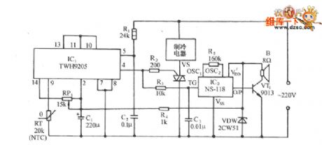
The figured circuit consists of the zero passage switch control circuit composed of TW9205 and its external elements, SCR drive system cool control circuit and sound generating circuit,etc. The figured temperature sensor RT is adopted with the backward temperature coefficient (NTC) thermistor, it is connected with the difference switch amplifier inverting input terminal (9-pin) in the TWH9205, and the forward input(13-pin) is connected with the 10-pin and 11-pin of LEV clamping pole, i.e the 13-pin is locked at a solid LEV. Adjust the value of RP1 and make TWH9205 output a low LEV in the set temperature range
(View)
View full Circuit Diagram | Comments | Reading(926)
The underwater pump burglarproof alarm circuit
Published:2011/6/30 23:09:00 Author:qqtang | Keyword: underwater pump, burglarproof alarm
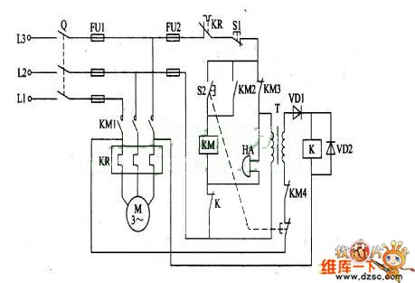
When the irrigating underwater pump is far from the working spot, it is easy to be stolen. The following is to introduce the underwater pump burglarproof alarm, which can deliver alarm signals when the pump is stolen or the pump is malfunctioning, reminding the user of handling in time. The working principle of the circuitThe pump alarm circuit consists of the relay K, diode VD1 and VD2, the power supply transformer T and ring HA, see as the figure.
(View)
View full Circuit Diagram | Comments | Reading(763)
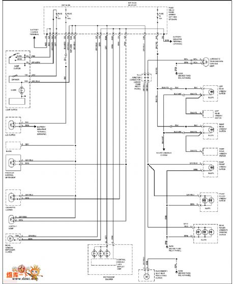
The Suzuki Antelope Century Star whole car circuit
Published:2011/6/30 22:59:00 Author:qqtang | Keyword: Suzuki, Antelope, Century Star, whole car
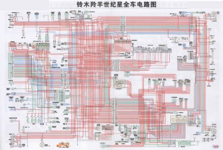
The Suzuki Antelope Century Star whole car circuit is shown as above.
(View)
View full Circuit Diagram | Comments | Reading(1092)
The Volkswagon chair heating circuit
Published:2011/6/30 22:54:00 Author:qqtang | Keyword: Volkswagon, chair heating
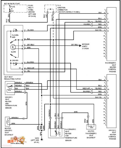
View full Circuit Diagram | Comments | Reading(476)
The Volkswagon instrument lighting circuit
Published:2011/6/30 22:56:00 Author:qqtang | Keyword: Volkswagon, instrument
View full Circuit Diagram | Comments | Reading(583)
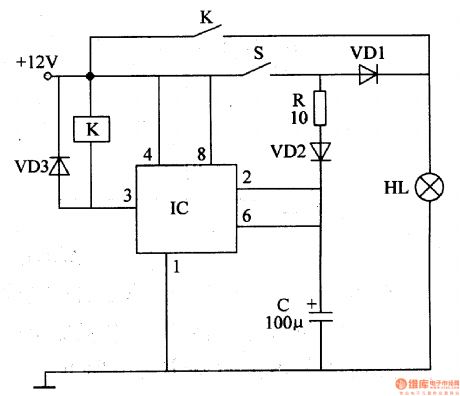
Motorcycle Illuminating Lamp Controller
Published:2011/6/30 6:18:00 Author:Sue | Keyword: Motorcycle, Illuminating Lamp, Controller

When the speed of the motorcycle is fast, C's voltage will be equal to GB's voltage. VD2,V1 and V2 are disconnected. K is released and AK1 is disconnected. K2 is connected. HL3,HL2,HL1 will be powered by G.
When the speed is slower than a certain value, C's voltage will make VD2 connected. V1,V2 are connected and K is connected. K1 is connected while K2 is disconnected. HL1-HL3 will be powered by GB.
When C is short, R1 will be disconnected to protect the circuit. (View)
View full Circuit Diagram | Comments | Reading(486)
Brake Flash Light
Published:2011/6/30 6:09:00 Author:Sue | Keyword: Brake, Flash, Light
When the oscillator begins to work, 300V high-frequency pulse voltage will be generated on W3. The voltage will be divided into four circuits after rectification. One will be put on the flash light's A terminal directly. One will charge C4. One will charge C3 through R2,R3. One will charge C2 through R2,R4,R5.
When C2-C4 stop charging, V2, VT will be connected. C3 will generate high voltage on T2. The voltage will be put on B,C. Then C2-C4 will be charged quickly. Everytime the brake switch is connected, the flash light will twinkle many times. (View)
View full Circuit Diagram | Comments | Reading(619)
Motor Fluorescent Lamp Circuit
Published:2011/6/30 6:24:00 Author:Sue | Keyword: Motor, Fluorescent Lamp, Circuit
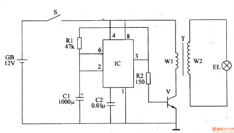
When S is connected, square wave oscillator will begin to work, and IC's pin 3 will output square wave pulse signals. When IC's pin 3 outputs high level, V is connected and T's W1 will have current. When IC's pin 3 outputs low level, V is disconnected and W1's current is cut off, W2 will generate high voltage. EL will be illuminated by the high voltage. (View)
View full Circuit Diagram | Comments | Reading(675)
| Pages:1643/2234 At 2016411642164316441645164616471648164916501651165216531654165516561657165816591660Under 20 |
Circuit Categories
power supply circuit
Amplifier Circuit
Basic Circuit
LED and Light Circuit
Sensor Circuit
Signal Processing
Electrical Equipment Circuit
Control Circuit
Remote Control Circuit
A/D-D/A Converter Circuit
Audio Circuit
Measuring and Test Circuit
Communication Circuit
Computer-Related Circuit
555 Circuit
Automotive Circuit
Repairing Circuit