
Circuit Diagram
Index 1651
Loom saves electricity controller 4
Published:2011/6/29 21:55:00 Author:Nicole | Keyword: loom, saves electricity controller
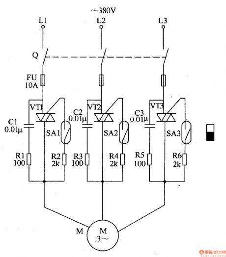
The loom saves electricity controller circuit is composed of knife switch Q, fuse FU, transistors VT1-VT3, resistors R1-R6, capacitors C1-C3, spring tubes SA1-SA2 and motor M, it is shown in the figure 8-20.
Knife switch Q is turned on, the loom's machine open and shut down handle is pushed blak of the start-up position, under the magneticaction of machine open and shut down handle's permanent magnet, the spring tubes SA1-SA2's control contact is connected, VT1-VT3 are triggered and turned on, motor M runs.
The sensitivity of V1-V3 trigger can be changed by adjusting R2, R4 and R6.
(View)
View full Circuit Diagram | Comments | Reading(540)
Simple light intensity meter circuit
Published:2011/6/30 3:48:00 Author:Christina | Keyword: Simple, light intensity, meter circuit

The simple light intensity meter circuit is as shown in the figure. The electric bridge circuit is composed of the VT1, R4, R5 and RP1. When there is no illumination, the adjustment potentiometer RP1 makes the balance of the bridge, and there is no current on the ammeter, the ammeter pointer indicates to zero. When the light irradiates on the photosensitive diode VD1, the photodiode shows the different resistances with the different light intensities, so the field effect current flows through the ammeter, the pointer deflects.
Figure: Simple light intensity meter circuit (View)
View full Circuit Diagram | Comments | Reading(2151)
AN5276 dual-channel audio power amplifier integrated circuit
Published:2011/6/30 3:55:00 Author:Christina | Keyword: dual-channel, audio power amplifier, integrated circuit

The AN5276 is designed as one kind of dual-channel audio power amplifier integrated circuit that can be used in the Panasonic, Sharp and Hitachi TV sets or the sound system's amplifier of the FuRi large screen color TV.
1.Features
The AN5276 is composed of two channels of power amplifier circuits with the same function, the static noise control circuit, the standby control circuit and the over temperature and short-circuit protection circuit, the output power of every channel is about 12.5W.
2.Pin functions and data
The AN5276 uses the 12-pin single row package, the pin functions and data are as shown in table 1.
Table 1 The pin functions and data of the AN5276
(View)
View full Circuit Diagram | Comments | Reading(1325)
AN5274 dual-channel audio power amplifier integrated circuit
Published:2011/6/30 3:58:00 Author:Christina | Keyword: dual-channel, audio power, amplifier, integrated circuit

The AN5274 is designed as one kind of dual-channel audio power amplifier integrated circuit which is produced by the Panasonic company, and it can be used in the large screen color TVs and the home audio equipments.
1.Features
The AN5274 is composed of two channels of power amplifier circuits with the same function, the static noise control circuit, the standby control circuit and the over temperature and short-circuit protection circuit, the output power of every channel is about 4W.
2.Pin functions and data
The AN5274 uses the 12-pin single row package, the pin functions and data are as shown in table 1.
Table 1 The pin functions and data of the AN5274
(View)
View full Circuit Diagram | Comments | Reading(814)
AN5273 dual-channel audio power amplifier integrated circuit
Published:2011/6/30 4:06:00 Author:Christina | Keyword: dual-channel, audio power, amplifier, integrated circuit

The AN5273 is designed as one kind of dual-channel audio power amplifier integrated circuit which is produced by the Panasonic company, and it can be used in the large screen color TVs and the home audio equipments.
1.Features
The AN5273 is composed of two channels of power amplifier circuits with the same function, the static noise control circuit, the electronic volume control circuit and the over temperature and short-circuit protection circuit, the output power of every channel is about 5W.
2.Pin functions and data
The AN5273 uses the 12-pin single row package, the pin functions and data are as shown in table 1.
Table 1 The pin functions and data of the AN5273
(View)
View full Circuit Diagram | Comments | Reading(693)
AN5026K infrared remote control signal receiving integrated circuit
Published:2011/6/30 6:39:00 Author:Christina | Keyword: infrared, remote control signal, receiving integrated circuit
The AN5026K infrared remote control signal receiving integrated circuit is produced by the Panasonic company that can be used in all kinds of electronic products' remote control systems such as the remote control fans, air conditioners, acoustics, TVs, DVD players.etc.
1.Features
The AN5026K is composed of the preamplifier circuit, the bandpass filter circuit, the automatic level control circuit, the wave detection circuit and the buffer amplification circuit.
2.Pin functions and data
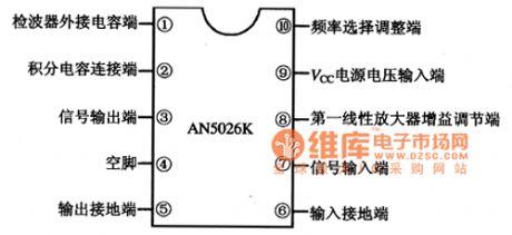
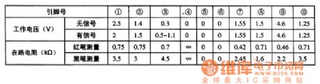
The AN5026K uses the 10-pin dual-row DIP package, the pin functions and data are as shown in figure 1, the operating parameters are as shown in table 1.
Figure 1 The pin functions and data of the AN5026K
Table 1 The operating parameters of the AN5026K
(View)
View full Circuit Diagram | Comments | Reading(459)
AN5265 audio power amplifier integrated circuit
Published:2011/6/30 4:19:00 Author:Christina | Keyword: audio power, amplifier, integrated circuit


The AN5265 audio power amplifier integrated circuit is produced by the Panasonic company that can be used in a variety of sound systems as the power amplifier.
1.The internal circuit block diagram
The AN5265 is composed of the electronic volume control circuit, the static noise control circuit and the audio output circuit.etc. The internal circuit block diagram is as shown in figure 1.
Figure 1 The internal circuit block diagram of AN5265
2.Pin functions and data
The AN5265 uses the single row 9-pin package, the pin functions and data are as shown in table 1.
Table 1 The pin functions and data of the AN5265
3.Typical application circuit
The typical application circuit is as shown in figure 2.
(View)
View full Circuit Diagram | Comments | Reading(7341)
AN5179NK intermediate frequency signal processing integrated circuit
Published:2011/6/30 4:43:00 Author:Christina | Keyword: intermediate frequency, signal processing, integrated circuit
The AN5179NK intermediate frequency signal processing integrated circuit is produced by the Panasonic company, and it can be used in the Panasonic TV sets.
1.Features
The AN5179NK uses the audio-visual standard separation mode and it can be used in the multi-channel audio circuit. The AN5179NK integrates the alto AGC, the high pitch AGC, the automatic frequency control circuit and the audio circuit.
2.Pin functions and data
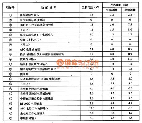
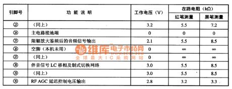
The AN5179NK uses the 30-pin dual-row DIP package, the pin functions and data are as shown in table 1.
Table 1. The pin functions and data of the AN5179NK
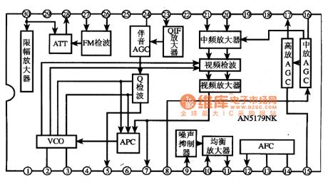
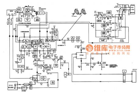
3.The internal circuit block diagram and the typical application circuit
The internal circuit block diagram and the typical application circuit are as shown in figure 1 and 2.
Figure 1 The internal circuit block diagram of the AN5179N
Figure 2. The typical application circuit of theAN5179NK
(View)
View full Circuit Diagram | Comments | Reading(697)
AN3788S switch pulse generating integrated circuit
Published:2011/6/30 6:47:00 Author:Christina | Keyword: switch, pulse, generating integrated circuit

The AN3788S switch pulse generating integrated circuit is produced by the Panasonic company that can be used in the cameras such as th Panasonic NV-M8000 camera.etc.
1.Features
The AN3788S is composed of the switch pulse generator, the error voltage comparator, the compare pulse inverter and other subsidiary circuits. The internal circuit block diagram is as shown in figure 1.
Figure 1 The internal circuit block diagram and the typical application circuit of the AN3788S
2.Pin functions and data
The AN37885 uses the 28-pin dual-row DIP package, the pin functions and data are as shown in table 1.
Table 1 The pin functions and data of the AN37885
3.Typical application circuit
The typical application circuit of the AN3788 is as shown in figure 1. (View)
View full Circuit Diagram | Comments | Reading(539)
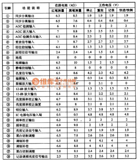
AN33215 brightness signal processing integrated circuit
Published:2011/6/30 6:59:00 Author:Christina | Keyword: brightness signal, processing, integrated circuit

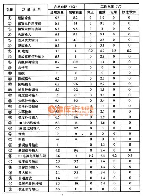
The AN33215 brightness signal processing integrated circuit is produced by the Panasonic company that can be used in the Panasonic AN-M series cameras.
1.Features
The AN33215 has the brightness signal demodulation and loss compensation processing circuit to process the replay video signal of the camera, and it bandpass filters, amplifies, limits and demodulates the replay brightness signal. The internal circuit block diagram of the AN3215S is as shown in figure 1.
Figure 1 The internal circuit block diagram and the typical application circuit of the AN3215S
2.Pin functions and data
The AN3321S uses the 32-pin dual-row DIP apckage, the pin functions and data are as shown in table 1.
3.Typical application circuit
The typical application circuit of the AN3321S is as shown in figure 1.
Table 1 The pin functions and data of the AN3321S
(View)
View full Circuit Diagram | Comments | Reading(487)
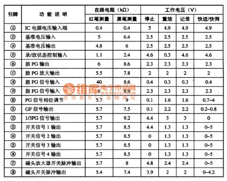
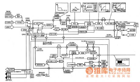
AN33215S brightness signal processing integrated circuit
Published:2011/6/30 7:11:00 Author:Christina | Keyword: brightness signal, processing, integrated circuit
The AN33215S brightness signal processing integrated circuit is produced by the Panasonic company that can be used in the Panasonic AN-M series cameras.
1.Features
The AN3215S's main function: it amplifies and modulates the FM brightness signal which is sent from the video magnetic head amplifier when it is replaying, and it reverts the FM brightness signal to the brightness signal, then the brightness signal composes of the video signal with the chroma signal. When it is recording, it AGC amplifies, black and white cute, and clamps the video signal to change it into the FM signal, this FM signal adds to the magnetic head amplifier to supply the recording signal for the video magnetic head.
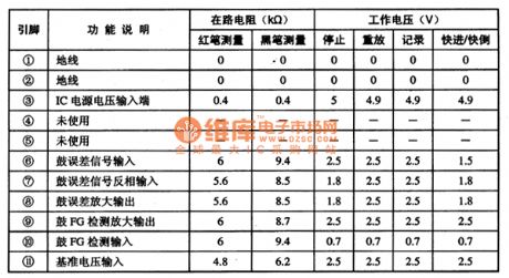
2.Pin functions and data
The AN3215S uses the 28-pin dual-row plastic structure, the pin functions and data are as shown in table 1.
Table 1 The pin functions and data of the AN3215S
3.Typical application circuit
The internal circuit block diagram and the typical application circuit are as shown in figure 1.
Figure 1 The internal circuit block diagram and the typical application circuit of the AN3215S
(View)
View full Circuit Diagram | Comments | Reading(492)
AIC1652 micro power consumption voltage reversal conversion integrated circuit
Published:2011/6/30 7:27:00 Author:Christina | Keyword: micro power consumption, voltage reversal, conversion, integrated circuit
The AIC1652 micro power consumption voltage reversal conversion integrated circuit is produced by the TaiWan
Peiheng company that can be used to adjust the contrast ratio of the LCD display screen's back bias voltage,
such as the notebook type computer, the portable communication device, the portable data collection terminal products, also the negative power supply.
1.Features
The AIC1652 is composed of the reference voltage circuit, the driver circuit, the current limit current-protection circuit, the power-off control circuit and other subsidiary circuits.
2.Main electrical parameters
The input voltage range of the AIC1652 is 2.4-7V, the output voltage range is -12-40V, the output current is about -10mA, the quiescent current is about 80μA, also it has the closing mode control.
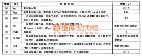
3.Pin functions and data
The AIC1652 has two kinds of packages, the AIC1652CN uses the DIP package, the AIC1652CS uses the SO package. The pin functions and data are as shown in table 1.
Table 1 The pin functions and data of the AIC1652
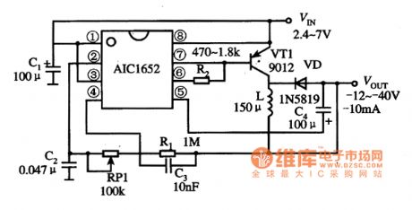
4.Typical application circuit
The Typical application circuit of the AIC1652 is as shown in figure 1
(View)
View full Circuit Diagram | Comments | Reading(1118)
Simple and practical TV lightning prevention protection circuit
Published:2011/6/24 22:25:00 Author:TaoXi | Keyword: Simple, practical, TV, lightning prevention, protection circuit

The application circuit of this device is as shown in the figure. When you are watching TV in the thunderstorm day, the thunder can damage the TV through two approaches: one is through the outdoor TV antenna; another is through the power line of TV. The former often damages the high frequency head, the latter often damages the power supply circuit of the line field output circuit. We can add the voltage dependent resistor on the outdoor antenna to prevent this consequence, the voltage dependent resistor needs to be connected with the ground. The application circuit connection method of the power protection part is as shown in figure 8.
(View)
View full Circuit Diagram | Comments | Reading(559)
resistance error gauge circuit with IC
Published:2011/6/18 10:15:00 Author:Nancy | Keyword: resistance error gauge, IC

The circuit uses voltage divider R5 and R7 to form a window descriminator connected to pin 8 of TCA965. The width of the window is adjusted by the voltage at pin 9. The width of the window can be set as 64mV(+US=12)by appropriately setting the value of R9 as 22Ω. Under small window width,the measurement accuracy is relative to the error of the R6 and R7. Since the circuit TCA963 output has 50mA load current, it can directly drive relay coil or LED. (View)
View full Circuit Diagram | Comments | Reading(556)
Temperature regulation circuit diagram used in valve control
Published:2011/6/18 10:04:00 Author:Nancy | Keyword: temperature regulation, valve control

Main technical data:operating voltage: 18Vtemperature range: 25 to 95 ℃sensor maximum allwable temperature: 100 ℃temperature bias under ±10% power supply fluctuation: <0.1°Kadjustable static area: 0.2 to 1°K (View)
View full Circuit Diagram | Comments | Reading(892)
preamplifer circuit with high impedance
Published:2011/6/18 10:29:00 Author:Nancy | Keyword: high impedance, preamplifer

Figure (a) and (b) has very high input resistor and very low output resistor and can be used as wideband amplifier for test head circuit such as oscilloscope, the input and output have the same electric potential, the voltage amplification factor is 1. Figure (c) is the amplitude and phase characteristic curve when load resistor RL equals to 50Ω.
Main technical data:input resistor (25℃)﹥109Ωwideband frequency (-3 dB, load resistor RL=50Ω)﹥100MHz output resistor﹤10Ω (View)
View full Circuit Diagram | Comments | Reading(556)
transmitter circuit with photo resistor
Published:2011/6/18 21:27:00 Author:Nancy | Keyword: photo resistor, transmitter

View full Circuit Diagram | Comments | Reading(689)
488kHz signal generator and frequency divider circuit
Published:2011/6/18 21:49:00 Author:Nancy | Keyword: 488kHz, signal generator, frequency divider
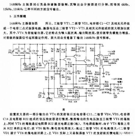
1488kHz master oscillator uses quartz crystal resonator to stabilize frequency, the output is divided by the frequency divider to obtain three different square wave outputs which are 4kHz, 12kHz and 124kHz.
Working principle:1488kHz master oscillator is shown as the circuit. Triode VT1, diode VD1, capacitor C1-C7 and related components form a capacitance connecting three point type oscillator circuit. The oscillating voltage is amplified by the amplifer composed by triode VT2-VT5 and related components. VT4 is emitter output which is featured with high input impedance, low output impedance, and increases the backward stage with load capacity and stabilize the forward stage oscillating signal. Transformer T outputs 1488kHz signal frequency after amplified. (View)
View full Circuit Diagram | Comments | Reading(681)
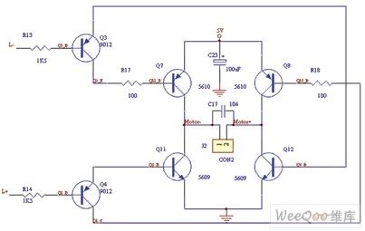
Left motor control circuit
Published:2011/6/18 21:59:00 Author:Nancy | Keyword: left motor
View full Circuit Diagram | Comments | Reading(470)
Gain or programming amplifier circuit
Published:2011/6/20 8:31:00 Author:Nancy | Keyword: Gain amplifier, programming amplifier

The circuit shown is a wide input range amplifier composed by PGA103. The 11.3kΩ and 102kΩ resistors form the voltage division circuit, the divider ratio is about 1/10, when the input voltage is 120V, the voltage added to PGA103 input after division is only 12V, therefore wide voltage input is available. Meanwhile, didoe D1, D2(1N4148) use as two-way clamp, making the input voltage of PGA103 ±15 to 士0.7V. (View)
View full Circuit Diagram | Comments | Reading(577)
| Pages:1651/2234 At 2016411642164316441645164616471648164916501651165216531654165516561657165816591660Under 20 |
Circuit Categories
power supply circuit
Amplifier Circuit
Basic Circuit
LED and Light Circuit
Sensor Circuit
Signal Processing
Electrical Equipment Circuit
Control Circuit
Remote Control Circuit
A/D-D/A Converter Circuit
Audio Circuit
Measuring and Test Circuit
Communication Circuit
Computer-Related Circuit
555 Circuit
Automotive Circuit
Repairing Circuit