
Circuit Diagram
Index 1659
Anti Lost Alarm (2)
Published:2011/6/29 6:21:00 Author:Sue | Keyword: Anti Lost, Alarm
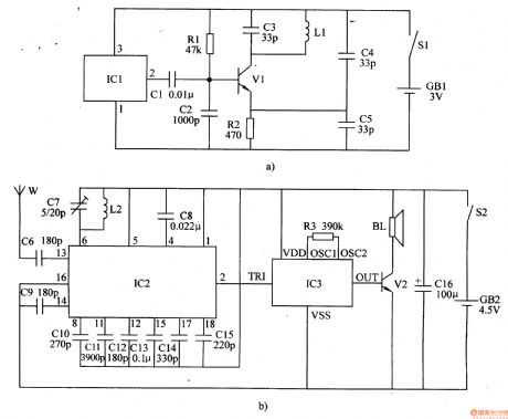
When S1 is connected, IC1 begins to work. Its pin 2 will output oscillate signals which will be emitted by L1.
When W receives the signals, IC2's pin 2 will output low level after the signals are transformed and amplified. IC2's pin 2 will output low level. IC3 doesn't work and BL makes no sound.
When to use the device and when the distance is beyond 5m, W will receive no signals. IC2's pin 2 will output high level. IC3 begins to work. The signals will promote BL to make an alarm sound after the signals are amplified by V2. (View)
View full Circuit Diagram | Comments | Reading(1347)
Anti Lost Alarm (1)
Published:2011/6/29 6:15:00 Author:Sue | Keyword: Anti Lost, Alarm
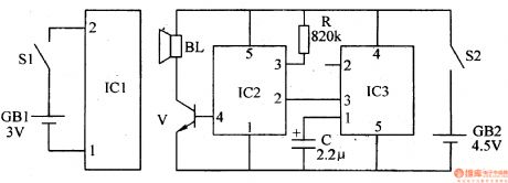
When the distance between the wireless transmitter and the wireless receiver is within 8m, IC2's inner tiny antenna will receive the high-frequency signals emitted by IC1's inner tiny antenna. IC2's pin 2 will output high level after the signals are amplified, detected, delayed and transformed. Its pin 3 will output low level. IC3 doesn't work and BL makes no sound.
When the distance is beyond 8m, the receiver will receive no signals. IC2's pin 2 will output low level and pin 3 will output high level. IC3 will be connected. The signals will promote BL to make an alarm sound after the signals are amplified by V. (View)
View full Circuit Diagram | Comments | Reading(934)
Plastic Bags Sealing Machine (3)
Published:2011/6/27 2:31:00 Author:Sue | Keyword: Plastic Bags, Sealing, Machine
When S1 is on, 220v voltage will generate 18v and 24v voltage after reduction. The 18v voltage will provide the heating control circuit and indicating circuit with working power. The 24v voltage will charge C2. HL1 is illuminated and V1-V3 are disconnected. K is released. EL is not heated and HL2 is not illuminated.
When S2's nomally closed interlock is disconnected, C2 will charge V1's b, and V2 V1 will be connected. K is connected and K2 K1 are connected. EH is heated. HL2 is illuminated. When C2 stops discharging, V1 V2 are disconnected and K is released. EH stops working. The bag is sealed. (View)
View full Circuit Diagram | Comments | Reading(1714)
Plastic Bags Sealing Machine (2)
Published:2011/6/27 2:24:00 Author:Sue | Keyword: Plastic Bags, Sealing, Machine
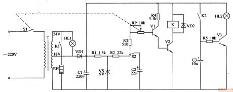
After putting the bag on EH, and push the handle, the 220v voltage will provide V with working power after reduction, rectification and filtration.
When the working power is on, V is disconnected. C1's voltage is put on VT and VT is connected. 220v voltage will be put on T through S and VT. Then it will provide EH with working power after reduction. Then EH will be heated and seal the bag. When C2's voltage reaches 0.7v, V is connected and EH stops working. When the handle is released, S is disconnected and C2 is discharged, prepared to charge for the next time. (View)
View full Circuit Diagram | Comments | Reading(1155)
Plastic Bags Sealing Machine (1)
Published:2011/6/27 2:17:00 Author:Sue | Keyword: Plastic Bags, Sealing, Machine
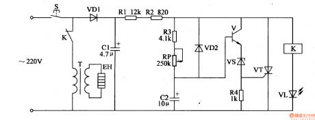
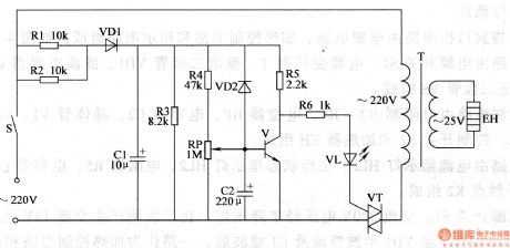
After S is pushed, 220V voltage will provide the circuit with 20v working voltage after rectification, filtration and reduction. V and VT are disconnected and K is connected. VL is illuminated and T begins to work. 220v voltage provides EH with working power and EH will seal the plastic bags. At the same time, C2 charges R3 by RP. When C2's voltage reaches a certain value, V is connected and VT is connected. K is released and VL is off. EH stops working.
When S is released, VT is disconnected and the circuit's working power is cut off. (View)
View full Circuit Diagram | Comments | Reading(2585)
Intermittent Current Controler (7)
Published:2011/6/26 4:56:00 Author:Sue | Keyword: Intermittent, Current, Controler
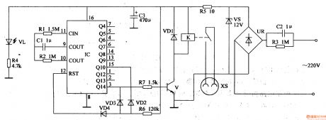
The 220v voltage will provide K and IC with 12v working voltage. VL is illuminated.
When IC begins to work, IC's pin 3 outputs high level and V is connected. K is connected. The working power is on. IC begins to count the working time of T. When timing work is over, IC's Q14 has low level and V is disconnected. K is released. IC's inner counter returns to normal and itgoes into the next period.
It works like this and realises the intermittent current control. (View)
View full Circuit Diagram | Comments | Reading(444)
Intermittent Current Controler (6)
Published:2011/6/26 4:46:00 Author:Sue | Keyword: Intermittent, Current, Controler

The 220v voltage can generate 12v voltage to provide the circuit with working power and VL1 will be illuminated.
The moment the power is on, IC's pin 2's and pin 6's voltages are lower than Vcc/3 and pin 3 outputs high level. VL2 is illuminated. K is connected. When voltages of pin 2 and pin 6 are higher than 2Vcc/3, IC's inner circuit will be reversed and K is released. VL2 is off. When voltages of pin2 and pin 6 are lower than Vcc/3, IC's inner circuit is reversed and pin 3 has high level again. K is connected and the working power is off. (View)
View full Circuit Diagram | Comments | Reading(486)
Intermittent Current Controler (5)
Published:2011/6/25 8:10:00 Author:Sue | Keyword: Intermittent, Current, Controler
When S is on, 220V voltage will provide the control circuit will +12V(Vcc) working voltage.
The moment S is on, IC's pin 2 will have low level and pin 3 will have high level. V and K is connected and K1,K2 are disconnected. The working power is on. IC's pin 2 and pin 6 's voltage will keep going up. When the voltagereaches 2Vcc/2, IC's pin 3 will have low level and V is disconnected. The power is cut off. When IC's pin 2 and pin 6 's voltage are going down and reaches Vcc/2, IC's pin 3 will output high level and V is connected. The working power is on again. (View)
View full Circuit Diagram | Comments | Reading(460)
Intermittent Current Controler (4)
Published:2011/6/25 8:02:00 Author:Sue | Keyword: Intermittent, Current, Controler

When S is on, 220V voltage will provide the circuits with 9V working voltage.
The moment S is on, IC's pin 2 has low level, and pin 3 outputs high level. K1 will be connected and A begins to work. VL1 is illuminated.
Then C1 will be charged and the voltage will keep going up. When the voltage exceeds 2Vcc/3, the inner circuit will be reversed and pin 3 will have a low level. A stops working and B begins to work. VL1 is off and VL2 is illuminated.
At the same time, when C1's voltage is lower than Vcc/3, IC's pin 3 will output high level and K1 is connected and K2 is disconnected. A begins to work and B stops working. (View)
View full Circuit Diagram | Comments | Reading(483)
Intermittent Current Controler (3)
Published:2011/6/25 7:56:00 Author:Sue | Keyword: Intermittent, Current, Controler

When S is on, 220V voltage will provide K with 15V working voltage and charge C3 by RP1. When C3's voltage reaches a certain value, VS2 will be connected and K is connected. The controled equipment begins to work. C3 will charge V1 and make V1 V2 connected. The equipment continues working. As C3's voltage keeps going down, and reaches 1.5 V, V1 V2 will be disconnected and K1 K2 will be disconnected. The controled equipment will stop working. C3 will be charged by RP1 again. (View)
View full Circuit Diagram | Comments | Reading(513)
Intermittent Current Controler (2)
Published:2011/6/25 7:52:00 Author:Sue | Keyword: Intermittent, Current, Controler
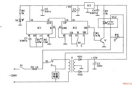
When the multivibrator begins to work, IC1's pin 3 will outputs square form pulse signals. IC2's pin 3 will output one high level every 10 or 6 minutes and when S3 is set on 1 , the controled equipment will work 1 min every 10 min. When S3 is set on 2 , the equipment will work 1 min every 6 min. V will be connected when IC2's pin 3 is connected and VLC's LED will be illuminated. The controled equipment will begin to work. (View)
View full Circuit Diagram | Comments | Reading(714)
Intermittent Current Controler (1)
Published:2011/6/25 7:46:00 Author:Sue | Keyword: Intermittent, Current, Controler

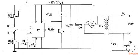
When the switch is on, the 220V voltage will be divided into 3 circuits. One provides K with 12V working voltage. One provides IC with 5.6V voltage. The other one illuminates VL3.
When IC begins to work, its pin 8outputs low level which will illuminate VL2. Then V1 V3 are disconnected and VL1 is illuminated.
When it stops working, its pin 8outputs high level, which will make V1 V3 connected and VL1 off and VL2 illuminated. (View)
View full Circuit Diagram | Comments | Reading(555)
Timing Controler (1)
Published:2011/6/25 7:33:00 Author:Sue | Keyword: Timing, Controler

When the swtich is turned on, +5v voltage will provide LED screenwith working power. IC will get electricity and GB will be charged.
When the time can be set, S2 will be used to set the hour and the minute. S3 will be used to add the time figure while S4 can be used to reduce the time figure. When it is in the timer function, S2 can be used to decide the working condition of the timer. When it is in running function, S2 is used to decide the manual state. S3 is used to start the power while S4 is used to cut off the power. (View)
View full Circuit Diagram | Comments | Reading(543)
Motor Phase Failure Protector (5)
Published:2011/6/28 7:02:00 Author:Sue | Keyword: Motor, Phase Failure, Protector
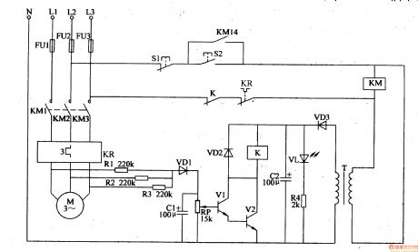
When S2 is pushed, the voltage between L2 and L3 will be put on KM through S1,S2,K,KR. KM will be connected. M begins to work. The other circuit will provide the drive circuit with 12V working voltage. At the same time, VL is illuminated.
When the three phases work well, V1 V2 are disconnected and K is released.
When there is phase failure, there will be a voltage between VD1 and N, which will make V1 V2 are connected after filtration and rectification. K is connected and KM is released. M's working power is cut off. (View)
View full Circuit Diagram | Comments | Reading(582)
Motor Phase Failure Protector (4)
Published:2011/6/28 6:55:00 Author:Sue | Keyword: Motor, Phase Failure, Protector
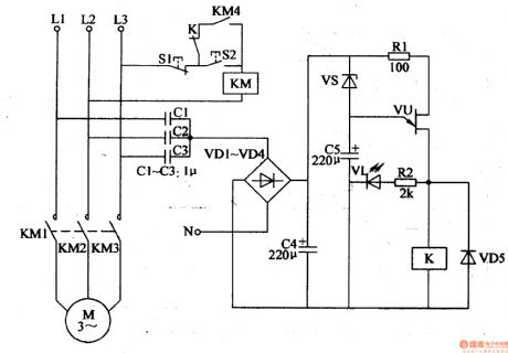
When the power works well,A has a low voltage and the voltage is not enough to make VS VU connected. K is not connected and M keeps working.
When there is phase failure, 12V voltage will be generated between A and N. The voltage will make VS connected. C5 begins to be charged. VU is connected and VL is illuminated. K is connected. KM is released and M's working power is cut off.
When the power returns to normal, VU is disconnected and K is released. When S2 is pushed the motor will start to work again. (View)
View full Circuit Diagram | Comments | Reading(1485)
Motor Phase Failure Protector (3)
Published:2011/6/28 6:50:00 Author:Sue | Keyword: Motor, Phase Failure, Protector
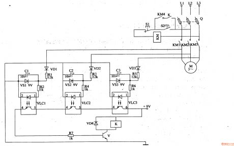
When S2 is pushed, KM is connected and KM1-KM4 are connected. M begins to work. LEDs in VLC1-VLC3 are illuminated. V is connected and K is connected. When S2 is released, KM keeps connected.
When there is phase failure, V is disconnected and K is disconnected. When S2 is released, KM is released and this will protect the circuit. (View)
View full Circuit Diagram | Comments | Reading(1513)
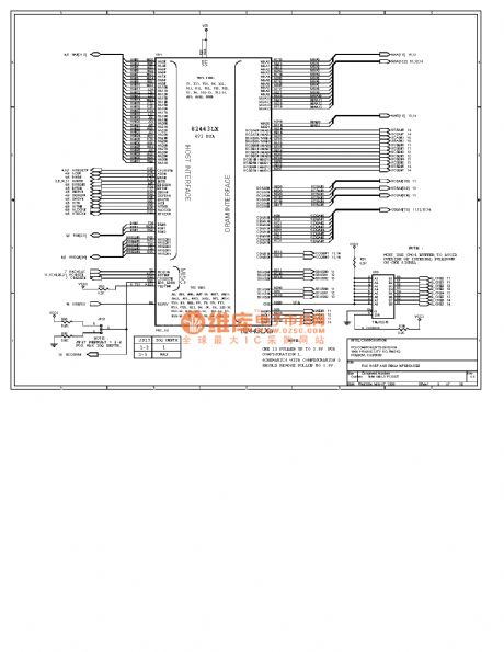
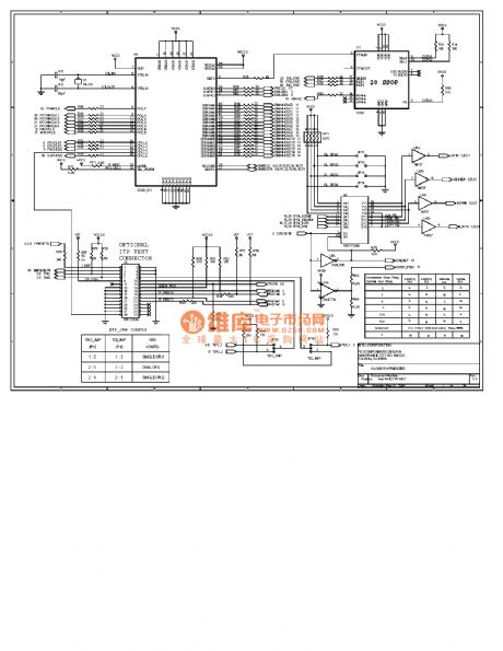
Computer Mainboard Circuit 440LX_08
Published:2011/6/24 3:27:00 Author: | Keyword: Computer Mainboard, 440LX_08
View full Circuit Diagram | Comments | Reading(553)
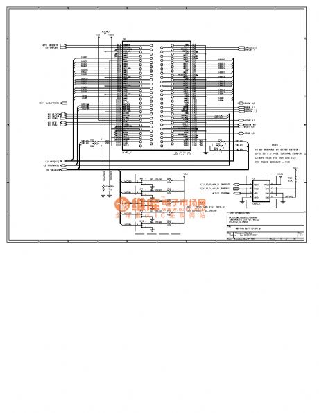
Computer Mainboard Circuit 440LX_07
Published:2011/6/24 3:32:00 Author: | Keyword: Computer Mainboard, 440LX_07
View full Circuit Diagram | Comments | Reading(494)
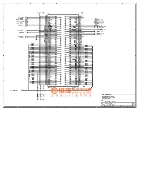
Computer Mainboard Circuit 440LX_06
Published:2011/6/24 3:58:00 Author:zj | Keyword: Computer Mainboard, 440LX_06
View full Circuit Diagram | Comments | Reading(466)
Computer Mainboard Circuit 440LX_05
Published:2011/6/24 3:59:00 Author:zj | Keyword: Computer Mainboard, 440LX_05
View full Circuit Diagram | Comments | Reading(462)
| Pages:1659/2234 At 2016411642164316441645164616471648164916501651165216531654165516561657165816591660Under 20 |
Circuit Categories
power supply circuit
Amplifier Circuit
Basic Circuit
LED and Light Circuit
Sensor Circuit
Signal Processing
Electrical Equipment Circuit
Control Circuit
Remote Control Circuit
A/D-D/A Converter Circuit
Audio Circuit
Measuring and Test Circuit
Communication Circuit
Computer-Related Circuit
555 Circuit
Automotive Circuit
Repairing Circuit