
Circuit Diagram
Index 1642
PGA202/203 circuit based on the numerical control gain programming instrument amplifier
Published:2011/7/1 1:11:00 Author:TaoXi | Keyword: numerical control, gain, programming instrument, amplifier

The PGA202/203 circuit based on the numerical control gain programming instrument amplifier is as shown in the figure:
(View)
View full Circuit Diagram | Comments | Reading(545)
Low power consumption program-controlled gain amplifier circuit
Published:2011/7/1 1:14:00 Author:TaoXi | Keyword: Low power consumption, program-controlled, gain, amplifier circuit

The Low power consumption program-controlled gain amplifier circuit is as shown in the figure:
(View)
View full Circuit Diagram | Comments | Reading(778)
Independent charger composed of the LP3945
Published:2011/7/1 1:16:00 Author:TaoXi | Keyword: Independent charger

View full Circuit Diagram | Comments | Reading(435)
Digital programmable amplifier circuit
Published:2011/7/1 1:18:00 Author:TaoXi | Keyword: Digital, programmable amplifier

The Digital programmable amplifier circuit is as shown in the figure:
(View)
View full Circuit Diagram | Comments | Reading(485)
Vizi saloon car ABS and brake light circuit
Published:2011/7/1 1:20:00 Author:TaoXi | Keyword: Vizi, saloon car, ABS, brake light
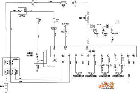
The Vizi saloon car ABS and brake light circuit is as shown in the figure:
(View)
View full Circuit Diagram | Comments | Reading(1036)
Vizi saloon car internal light, cigar lighter and remote control rearview mirror circuit
Published:2011/7/1 1:21:00 Author:TaoXi | Keyword: Vizi, saloon car, internal light, cigar lighter, remote control, rearview mirror
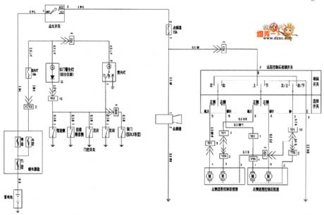
The Vizi saloon car internal light, cigar lighter and remote control rearview mirror circuit is as shown in the figure:
(View)
View full Circuit Diagram | Comments | Reading(400)
MAX846A typical application circuit
Published:2011/7/1 1:23:00 Author:TaoXi | Keyword: typical application

View full Circuit Diagram | Comments | Reading(487)
Vizi tail light and lighting circuit
Published:2011/7/1 1:24:00 Author:TaoXi | Keyword: Vizi, tail light, lighting circuit
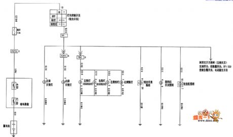
The Vizi tail light and lighting circuit is as shown in the figure:
(View)
View full Circuit Diagram | Comments | Reading(425)
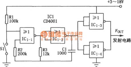
CD4001 single channel modulator circuit
Published:2011/7/1 0:41:00 Author:chopper | Keyword: single channel, modulator circuit
View full Circuit Diagram | Comments | Reading(782)
Panda 3643 infrared remote-control emitter circuit
Published:2011/7/1 0:42:00 Author:chopper | Keyword: Panda, infrared remote-control, emitter circuit
View full Circuit Diagram | Comments | Reading(507)
positive-negative double supply circuit
Published:2011/6/28 6:31:00 Author:chopper | Keyword: positive-negative, double supply circuit

The picture is a positive-negative double supply circuit which is usually adopted in the analog circuit.It is a power sipply circuit formed by tapped full-wave rectification and three terminal regulator.The ground of smoothing capacity C1,C2 and regulator is connected to A point on the tapped landline of transfer. Point A is a reference potential.The supply output will not be effected by the smoothing current of C1 and C2.
(View)
View full Circuit Diagram | Comments | Reading(516)
down-lead of high frequency circuit
Published:2011/6/27 9:30:00 Author:chopper | Keyword: down-lead, high frequency circuit
In the high frequency circuit,the inductance and capacitance of the down-lead effect circuit a lot and the supply lead is very important.We should reduce the impedance of landlines as possible as we can in the high frequency range.As for high frequency circuit, it includes landlines basically besides element lines and signal lines.Thus,all parts of the groud of the circuit can be connected by any routes and the impedance among the groud is very low.The picture a,b are printed plate wiring examples of single pipe broadband amplifier circuit.We can know there are all landlines besides down-leads.
(View)
View full Circuit Diagram | Comments | Reading(502)
example of A/D and D/A converter circuit
Published:2011/6/27 10:00:00 Author:chopper | Keyword: example, A/D and D/A, converter
The picture is the typical instance of digital analog circuit,and it is a A/D and D/A converter circuit.The A/D and D/A integrated chip is on the edge of the digital circuit and analog circuit.Thus,these chips include AGND and DGND,and there is no current going through the ground,the leads need not too thick.
(View)
View full Circuit Diagram | Comments | Reading(516)
landlines of digital and analog circuit on the same placode circuit
Published:2011/6/27 10:13:00 Author:chopper | Keyword: landlines, digital and analog circuit, same placode

When the digital circuit and analog circuit are on the same placode,the trend of the landlines is very important to prevent the noise of digital circuit from mixing into the analog circuit to effect its performance.The digital circuit and analog circuit must be separated physically if they are on the same circuit,because the analog ground AGND and digial ground DGND should be separated definitely.AGND and DGND should be connected at one point,just as picture a,b.
(View)
View full Circuit Diagram | Comments | Reading(513)
power supply and landlines of digital circuit
Published:2011/6/27 21:07:00 Author:chopper | Keyword: power supply, landlines, digital circuit

As to digital circuit,the impedance of power supply should be low as possible as we can.The high impedance will effect the circuit.The picture is a connection method of double-sided printed circuit board.On the element installation surface there are horizontal and longitudinal leads,and leads should be short and thick as possible as we can.Additionally,the leads are in grid shape to reduce the circuit impedance when the frequency is high.The waxy capacitance of power supply can reduce the high frequency impedance of leads of power supply.Thus,every IC is connected with a 0.1μF ceramic capacitor.To reduce the low frequency impedance of leads of power supply,we can add a 100μF electrolytic capacitor to the input end of power supply.
(View)
View full Circuit Diagram | Comments | Reading(536)
one point connetion method of amplification circuit
Published:2011/6/27 22:15:00 Author:chopper | Keyword: one point connetion method, circuit

Thus,it needs one point connetion method.The so-called one point connetion means the reference potentials of every part are the same.The picture a,b is the one point connetion method.As the picture (a),the ground of input end and amplifier is connected to the ground of power supply by one line.Therefore,all return current is circulated between the input signal ground and the amplifier.If among the benchmark ground there is a wiring resistor RC,it will generate noise and hum.
(View)
View full Circuit Diagram | Comments | Reading(615)
landlines of low frequency circuit
Published:2011/6/27 21:59:00 Author:chopper | Keyword: landlines, low frequency circuit

In the low frequency circuit,different grounding methods will effect a lot to the circuit performance when deal with the weak level signal.The picture a,b are the grounding methods of amplifier circuit.The picture (a) is a inverse amplification circuit,and it takes the same phase input terminal of operational amplifier as benchmark by connecting it to ground through resistor to amplify.The picture(b) is a in phase amplification circuit and it takes the inverse input end of operational amplifier as benchmark by connecting it to ground through resistor to amplify.
(View)
View full Circuit Diagram | Comments | Reading(592)
Limited current circuit with transistor
Published:2011/6/27 21:44:00 Author:chopper | Keyword: Limited current circuit, transistor

The picture is a limited current circuit with operational amplifier.In the circuit,R9 and R10 are used to detect output current.When the voltage drop is more than 0.6V,VT1 and VT2 will stop to cut off current.In this case,the current of VT3 and VT4 is limited within 400mA. (View)
View full Circuit Diagram | Comments | Reading(1349)
10W audio power amplification circuit of μPC1238
Published:2011/6/22 20:45:00 Author:chopper | Keyword: 10W, audio power, amplification

The picture shows a 10W audio power amplification circuit.This circuit adopts integrated power amplifier μPCI238 as the amplifying device.The input signal is added to the in-phase input end(pin 1) of operational amplifier through coupling capacitance(capacity is lμF) and resistor(resistance is 56kΩ).Between the output end (pin 4) and inverting input end(pin 2) is a feedback resistor R1 whose value is 56Ω,and between the inverting input end and groud are resistor R2 whose value is 1KΩ and a 22μF capacitor.The voltage amplification times of the circuit is:Av=(1+R1/R2)≈(1+56/1)=57 (View)
View full Circuit Diagram | Comments | Reading(1494)
NE556 automatic monitoring circuit of starting battery of dynamo
Published:2011/6/20 6:22:00 Author:chopper | Keyword: automatic monitoring, starting battery, dynamo

This is a automatic monitoring circuit of starting battery of dynamo,and it can detect the voltage state of storage battery continuously.When the battery discharges to the prescriptive lowest voltage,it will stop charging automatically;when the battery needs a charger but the charge power supply is not available,it can distinguish automatically and send out a acoustic signal to remind operating staff of power supply.In addition,it has a function of automatic-manually operation convertion,which makes it charge the battery at any time manually.
(View)
View full Circuit Diagram | Comments | Reading(3112)
| Pages:1642/2234 At 2016411642164316441645164616471648164916501651165216531654165516561657165816591660Under 20 |
Circuit Categories
power supply circuit
Amplifier Circuit
Basic Circuit
LED and Light Circuit
Sensor Circuit
Signal Processing
Electrical Equipment Circuit
Control Circuit
Remote Control Circuit
A/D-D/A Converter Circuit
Audio Circuit
Measuring and Test Circuit
Communication Circuit
Computer-Related Circuit
555 Circuit
Automotive Circuit
Repairing Circuit