
Circuit Diagram
Index 1647
MHz-LC Series Emitter Module Circuit Diagram
Published:2011/6/19 4:21:00 Author:Vicky | Keyword: MHz-LC Series Emitter Module

TXM-433/418/315 MHz-LC series module is a low-cost emitter module. It is used with LC series receptor and can transmit analog and digital signal for over 91.5 min (300 ft). LC series requires no tuning device or exterior RF components (except antenna). It is available to be applied in fields such as remote control, remote monitoring, industry process monitoring, periodic data transfer, illuminator control, safe/fire alarm, keyless typing system, medical monitoring/calling system and wireless data transfer etc.
Main technical features are listed as follows:
·Work frequency: 433/418/315 MHz;
·Direct analog or digital input;
·Data transfer rate: greater than 5 Kb/s;
·Voltage of power supply: 2.7~5.2 V;
·Maximum work current: 6MA, sleep mode current: l.5 μA;
·Output power: -4~4 dBm;
·Direct series interface. (View)
View full Circuit Diagram | Comments | Reading(1077)
MHz-RM Series FM/FSK Emitter Module Circuit Diagram
Published:2011/6/19 4:23:00 Author:Vicky | Keyword: MHz-RM Series FM/FSK Emitter Module

TXM-433/418 MHz-RM series is emitter moduel based on SAW. It is used with RM series receptor and can transmit analog and digital signal for over 152.5m (500 ft). RM series module requires no tuning, regulating or exterior RF component (except antenna). It is available to be applied in fields such as remote monitoring, industry process monitoring, periodic data transfer, illuminator control, safe/fire alarm and remote control etc.
Main technical features are listed as follows:
·Direct analog or digital input;
·Data rate: greater than 10 Kb/s;
·Voltage of power supply: 5.9~9 V;
· Work current: 6 mA.
(View)
View full Circuit Diagram | Comments | Reading(882)
Thyristor Work Performance Quick Test Circuit Diagram
Published:2011/6/26 6:12:00 Author:Vicky | Keyword: Thyristor Work Performance Quick Test
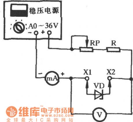
Plug the diode VD under test into sockets X1 and X2. Stabilized power supply adds reverse breakdown voltage to VD and the stabilized voltage value Uz can be read from voltage meter V, and the stable-working current value can be read from the milliammeter mA which is cascaded in the circuit. The indicating value in the mA will varies with the regulation of potensiometer RP. Observe the changing of the voltage meter, the less the stabilized value Uz changes, the better. (View)
View full Circuit Diagram | Comments | Reading(1404)
Semiconductor Diode Detecting Circuit Diagram
Published:2011/6/26 4:22:00 Author:Vicky | Keyword: Semiconductor Diode Detecting Circuit

Semiconductor diode is often used in electrical engineering circuit. Once the original diode breaks, it should replaced. Whether the new diode is good or not can be judged in the way as the picture shows. As shown in the picture, T is a 220/3V-2W power transformer, VD1 & VD2 are 2CP10 rectifier diodes, H1 & H2 are luminous diodes, and VDX is a diode under test. During the testing, plug the VDX into sockets X1 &X2. If only one luminous diode sends out light when the power is on, then the diode is good; however, if H1 & H2 both are luminous, it indicates that the VDX suffers internal short-circuit; if both are lightless, it indicates that the diode suffers internal open-circuit. (View)
View full Circuit Diagram | Comments | Reading(797)
Straight-Flow Capacitance Tester Circuit Diagram
Published:2011/6/16 10:56:00 Author:Vicky | Keyword: Straight-Flow Capacitance Tester
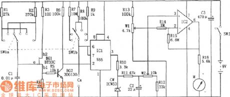
The above picture is a straight-flow capacitance tester. The test is composed of pulse generator, monostable trigger, DC amplifier ( direct current amplifier) and head indicating circuit etc. It can test capacitance from npF to 10μF. The distance is from to 100PF, from 0 to 1nF, from o to 10nF, from 0 to 100nF,from 0 to 1μF, and from 0 to 10μF. (View)
View full Circuit Diagram | Comments | Reading(764)
analyze encryption chip, encryption IC, DM2016, the copy plate chip, the copy plate IC, hardware encryption
Published:2011/6/18 23:09:00 Author:Nancy | Keyword: encryption chip, encryption IC, the copy plate chip, hardware encryption
Details:1. support I2C bus standard;2. support two bits I2C address selection;3. built-in 128 bits secret key and one-time burn;4. built-in 1024 bits E2PROM, 24C0X series IC compatible;5. SOP8 package;6. compliant with SGS
It uses a random number to produce a clear text, the special algorithm and secret key (OTP) are written unreadable one time, and buit in with 1028 Bit E2PROM. The personalized product has strong patent warranty. It has been widely used in GPS, BLUETOOTH, DV, LCD TV, DVD Car Player, DVR, Digital Photo Frame, Simulator and other embedded systems. (View)
View full Circuit Diagram | Comments | Reading(787)
Non-contact sensor alarm circuit
Published:2011/6/24 10:54:00 Author:Fiona | Keyword: Non-contact, sensor alarm

G is representative of sensors in the picture,there is a distributed capacitance Co existing between G and ground, capacitance three-point oscillator composed of Co and L, C1, V1,in the return circuit composed of Co, C1, L,in the view of alternating current path,C0 and C1 are connected in series. When no one is close to G,Co is small,when it connected in series with C1, both ends of the partial pressure of Co is greater than both ends of the partial pressure of C1,the both ends high frequency voltage of Co is fed to V1 base through C3,it's enough to keep three-point oscillator to produce oscillation.
(View)
View full Circuit Diagram | Comments | Reading(923)
Circuit Diagram of Capacitance/Frequency/Transistor Online Detector composed of 555
Published:2011/6/26 1:05:00 Author:Vicky | Keyword: Capacitance/Frequency/Transistor Online Detector
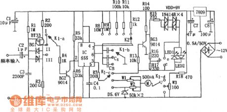
When K1 is placed in II, then it can be used to test capacitance. 555, resistances from R8 to R12 and Capacitance Cx under test constitute monostable timing circuit. The larger the capacity of Cx is, the wider the pulse is. That is to say, if td=1.1(R8~R12)Cx is larger, the average current value is larger, and the indication of correspondent header is larger. In the circuit, BG1 is a unijunction transistor, and constitutes relaxation oscillator together with R1 and C3. Its output oscillator pulse signal is the trigger pulse of IC.
When K1 is place in III, it can be used to test frequency. Under such circumstance, monostable circuit IC sends out fixed-width-value signal (td'=1.1(R8~R12)CB).
When K1 is place in I, it can be used to test transistor. Transistor BG1 is responsible for the conversion of the positive and negative power. (View)
View full Circuit Diagram | Comments | Reading(823)
Load sensor LSE application circuit
Published:2011/6/25 10:09:00 Author:Fiona | Keyword: Load sensor

The device's electrical circuit is shown as the below picture.Plug in CT, because the normally closed contact j1 of the relay J is closed,the lamp H lights, and because the normally open contact j2 breaks,④ pin of the LSE outputs the low level,at this time the transistor VT conducts.When VT conducts,the relay J is closed, contact j1 breaks,H breaks,at the same time,the contact j2 is closed, so t④ pin of the LSE outputs the high level, transistor VT breaks,the relay J releases,the contact j1 closes again, H is lit, contact j2 breaks again ... ... so the work cycles to cycle, leading to the lamp H flashing.
(View)
View full Circuit Diagram | Comments | Reading(755)
Catoptric-Strength Testing Circuit (CD4052B,CD40118) Diagram
Published:2011/6/26 1:01:00 Author:Vicky | Keyword: Catoptric-Strength Testing Circuit

When the circuit works regularly, make the infrared luminous diode (LED) out of light, the photodiode changes the received exterior interference signal into electrical signal, and then pass it to negative-direction integration circuit. Suppose this procession takes time of T1. Next, make the LED give out light, the photodiode changes the received photosignal into electrical signal and then pass it to positive –direction integrator circuit. Suppose this procession takes time of T2. Suppose T1=T2. Then the held signal the circuit displays is not relevant with exterior disturbing, but only relevant to the strength of the catoptic. Time of holding the signal is called holding time and marks it as T3. The reset time of correspondent integrator is T4. (View)
View full Circuit Diagram | Comments | Reading(1186)
Radio Digit-Type Frequency Display (C040,556) Circuit Diagram
Published:2011/6/26 0:56:00 Author:Vicky | Keyword: Radio Digit-Type Frequency Display
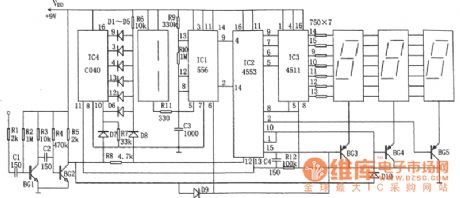
The above picture is radio digit-type frequency circuit diagram. The circuit is double time based circuit 556(IC1), BCD-code three-digit counter IC2(MC4553), twelve binary-system serial counter/frequency-divider IC4(C040), BCD-code seven-phase latch/ decoder/driver, four luminous Nixie tube LED etc. (View)
View full Circuit Diagram | Comments | Reading(2286)
Pressure sensor with filter and amplification circuit
Published:2011/6/26 8:34:00 Author:Fiona | Keyword: Pressure sensor, filter and amplification
MAX4471 is amplifier.MAX9028 is the MAXIM company's low power comparator.Filter circuit uses band-pass filter composed of MAX267(allowing 0.8 ~ 38Hz signal through),filters out the DC component of the signal,power,the high-frequency noise and frequency interference of the skin with the cuff friction,then further amplifies through the MAX4471,gets the matching chip voltage signal into the ADC2,monitors the AC component of blood pressure.While the signal is converted into pulse signals through a low-power comparator MAX9028 to trigger ADC1 work.
(View)
View full Circuit Diagram | Comments | Reading(583)
Circuit Diagram of Audio Frequency Indicator (FD502) Composed of Five-Digit LED Display
Published:2011/6/26 0:55:00 Author:Vicky | Keyword: Audio Frequency indicator, Five-Digit LED Display

The above picture is a circuit diagram of audio frequency indicator (FD502) which is composed of five-digit LED display. The circuit constitutes a level meter driver FD502 and a five-digit LED display. The circuit can generate DC level by extracting the positive variation amplitude, and thereby indicate the audio frequency. If the audio signal is too low, use FD501 to replace FD502 and then drive LED after preamplification. FD502and FD501 are domestic integrated circuits. FD501 has one preamplifier and 5 comparators inside, while FD502 has no preamplifier. (View)
View full Circuit Diagram | Comments | Reading(1105)
Acousto-optic Controlling Electronic Guidepost Circuit Diagram
Published:2011/6/23 8:51:00 Author:Vicky | Keyword: Acousto-optic Controlling Electronic Guidepost Circuit Diagram

Automatic guidepost circuit is shown in the above picture. It is mainly made of sound-controlling circuit, oscillating circuit and display driving system etc. (View)
View full Circuit Diagram | Comments | Reading(496)
TA7508P karaoke reverberation audio amplifition integrated cirucit
Published:2011/6/17 6:30:00 Author:chopper | Keyword: karaoke, reverberation audio, amplifition, integrated cirucit

TA7508P is a audio amplifition integrated circuit produced by Company TOSHIBA,and it is used as a reverberant acoustics signal generated by amplifition and delay on Konka BT5001 RPTV. TA7508 is one model of the TA7508P integrated circuits whose power is greater than TA7508 and it adopts 35V power supply,while TA7508 adopts 12V power supply.The functions of pins of the two are the same.TA7508 integrated circuit is applied to Konka BT5001 RPTV.Its function and data of integrated circuit is shown as chart 1.
(View)
View full Circuit Diagram | Comments | Reading(627)
Matsushita shaver charge circuit
Published:2011/6/14 3:17:00 Author:chopper | Keyword: Matsushita, shaver, charge

View full Circuit Diagram | Comments | Reading(1482)
TA7508 quad operational amplifier integrated circuit
Published:2011/6/16 0:52:00 Author:chopper | Keyword: quad operational, amplifier, integrated circuit


TA7508 is a quad operational amplifier integrated circuit.It belongs to general device.and it is applied to TV acoustics,music center and so on.1.The inner circuit and the function of pins of TA7508 TA7508 integrated package includes four same operational amplification circuit.The inner circuit is shown as the picture 1.This IC adopts the structure of 14 pins biserial plastic package.And it is applied to the Changhong NC-3 cassette mechanism colorcast karaoke circuit.The function and data of pins of integrated circuitare shown as chart 1.
2.TA7508 typical application circuitTA7508 integrated package is applied to the Changhong NC-3 cassette mechanism colorcast karaoke circuit.Its typical application circuit is shown as picture 2. (View)
View full Circuit Diagram | Comments | Reading(656)
STR-S6709 switch power supply thick film integrated circuit
Published:2011/6/15 8:05:00 Author:chopper | Keyword: switch power supply, thick film, integrated circuit

STRS6709 is a PWN control integrated circuit of current mode,and it is applie (View)
View full Circuit Diagram | Comments | Reading(1265)
printed circuit board with enough creepage distance in the high voltage circuit
Published:2011/6/15 5:13:00 Author:chopper | Keyword: printed circuit board, creepage distance, high voltage circuit


In the power supply circuit,there should be enough interval among lines for security.The interval is usually called creepage distance. A side circuit often should be added 220V voltage or above,therefore we needa creepage distance that can stand the high voltage.The usual creepage distance is 5OOV/1mm.But the distance is not enough if it is used in the high humidity environment.In this case, non-corroding resin should be printed on the surface of printed plate and so does the dampproof coating.Additionally,high voltage circuit can increase creepage distance by slotting the lines,just as follows.
(View)
View full Circuit Diagram | Comments | Reading(1273)
Principle and Circuit of Single Metal and Resistance Bridge Touch Switch
Published:2011/6/28 6:05:00 Author:Michel | Keyword: Principle and Circuit, Single Metal, Touch Switch, Resistance Bridge

Singal Metal Touch Switch's Principle and Circuit
Work's PrincipleThe circuit shown in the picture 1 only uses a piece of sheet metal.The circuit adoptes two pieces of Schmitt triggers 4093(There are four same ends but only two of them are input ends in the circuit,such as CD4093 and TC4093.).Usually,the diode LED1 does not spark whenthe third feet of IC2-a output terminal is in low PWL.And the output terminal changes into high PWL when it touches sheet metal,which makes the LED1 glow.The figure 2 is similar to figure 1 and it uses less devices and contorl the voltage by outputing electric keys directly. (View)
View full Circuit Diagram | Comments | Reading(762)
| Pages:1647/2234 At 2016411642164316441645164616471648164916501651165216531654165516561657165816591660Under 20 |
Circuit Categories
power supply circuit
Amplifier Circuit
Basic Circuit
LED and Light Circuit
Sensor Circuit
Signal Processing
Electrical Equipment Circuit
Control Circuit
Remote Control Circuit
A/D-D/A Converter Circuit
Audio Circuit
Measuring and Test Circuit
Communication Circuit
Computer-Related Circuit
555 Circuit
Automotive Circuit
Repairing Circuit