Circuit Diagram
Index 1652
Based on BP01 type pressure sensor blood pressure sensor circuit
Published:2011/6/29 0:59:00 Author:Fiona | Keyword: Based on BP01 type pressure sensor
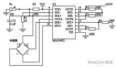
The circuit uses BP01-type pressure sensor and amplifier MAX4472. BP01-type pressure sensor is specifically designed for the detection of blood pressure, and is mainly used for portable electronic device.It uses precision thick-film ceramic chip and nylon plastic packaging,it has the characteristics of a high linear, low noise and external stress of small;it uses the internal calibration and temperature compensation mode to improve the measurement accuracy, stability and repeatability, in the whole range,the precision is ± 1%, zero offset is not greater than ± 300μV.MAX4472 is the MAXIM company's a low power consumption chip which integrates four operational amplifiers.
(View)
View full Circuit Diagram | Comments | Reading(2696)
telecommunication equipment power measurement circuit
Published:2011/6/23 9:52:00 Author:Nancy | Keyword: telecommunication equipment, power measurement


This article discusses how to measure the input voltage and current of telecommunication equipment which adopts two independent inputs (-48V(A) and -48V(B)). Each independent input voltage range is not norrow than -42.5V~-56.5V, and OR operation is used on the module for this two independent inputs with the consideration of redundance.From the point of maintenance and support, it is very important to measuring the input voltage, the power of the module and wether the input exsits.
Figure 1 is the simplified front end of the common power supply part of the telecommunication equipment. The OR operation of the two inputs is made by D1 and D2. Once the voltage through OR operation is higher than low-voltage threshold determined by R1 and R2, hot plug circuit (U1) add the electricity gradually for the load (data processing).
(View)
View full Circuit Diagram | Comments | Reading(1169)
PHILIPS 170B4 LCD Monitor Switch Power Supply Circuit
Published:2011/6/30 4:31:00 Author:Joyce | Keyword: PHILIPS 170B4 , LCD Monitor , Switch , Power Supply

PHILIPS 170 B4 LCD monitor switching power supply takes 7101 (TEA1533) as its core component. The circuit is as shown in the figure. (View)
View full Circuit Diagram | Comments | Reading(7196)
24V Short-circuit Prevention and Regulated Power Supply Circuit
Published:2011/6/30 4:26:00 Author:Joyce | Keyword: 24V , Short-circuit, Prevention , Regulated , Power Supply

Short-circuit prevention and regulated rower supply circuit is shown as follows: (View)
View full Circuit Diagram | Comments | Reading(915)
The releasing interfere and preventing thief dozen circuit
Published:2011/6/30 3:19:00 Author:Fiona | Keyword: The releasing interfere, preventing thief dozen

The releasing interfere and preventing thief dozen circuit is shown as below,T,R is the phone into the line side,telephone is connected to the A, B-side.When the user uses the telephone,the burglar alarm does not work. When a theft or fight occurs, the line voltage reduces,transistor V1 is cut-off, base V2 obtains the high potential to be conducted,V3 is conducted too,so that there is output voltage on the stabilivolt VD3,the oscillator has electricity,the oscillator has electricity through the C6 input,the C6 output oscillation voltage to the telephone line,disturbs the pirates caller.
(View)
View full Circuit Diagram | Comments | Reading(591)
0~30V﹑2A-based Constant Current and Regulated Power Supply Circuit
Published:2011/6/30 4:39:00 Author:Joyce | Keyword: 0~30V﹑2A-based , Constant Current , Regulated Power Supply
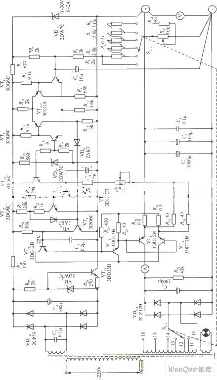
0~30V﹑2A-based constant current and regulated power supply circuit is shown in the following figure. (View)
View full Circuit Diagram | Comments | Reading(1414)
A Durable 3~120V Regulated Power Supply Circuit
Published:2011/6/30 4:41:00 Author:Joyce | Keyword: Durable , 3~120V , Regulated Power Supply

A durable 3~120V regulated power supply circuit is as shown in the figure. (View)
View full Circuit Diagram | Comments | Reading(1039)
110V Regulated Power Supply Circuit with Stable Performance
Published:2011/6/30 4:43:00 Author:Joyce | Keyword: 110V , Regulated Power Supply , Stable Performance
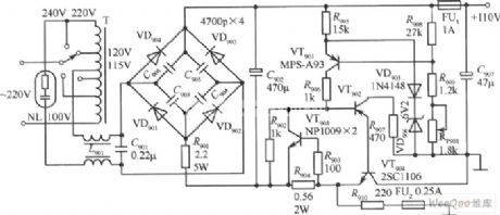
110V regulated power supply circuit with stable performance is as shown in the figure. (View)
View full Circuit Diagram | Comments | Reading(3430)
70V Regulated Power Supply Based Circuit
Published:2011/6/30 4:45:00 Author:Joyce | Keyword: 70V , Regulated Power Supply , Based

70V regulated power supply based circuit is as shown in the figure.
(View)
View full Circuit Diagram | Comments | Reading(927)
Ordinary 1000 V High Voltage Output DC Regulated Power Supply Circuit
Published:2011/6/30 4:35:00 Author:Joyce | Keyword: Ordinary , 1000 V , High Voltage, Output , DC , Regulated Power Supply

Ordinary 1000 V high voltage output DC regulated power supply circuit is as shown in the figure. (View)
View full Circuit Diagram | Comments | Reading(722)
Hands-free telephone terminal circuit
Published:2011/6/29 1:49:00 Author:Fiona | Keyword: Hands-free telephone terminal

Conference call terminal is made by the hands-free phone chips, high-quality hands-free phone chips MC34118 ensure the properties of the machines is reliable,elements connected way and the parameter selection of the part pins in the circuit components in the connection and parameters chose retaining the original MC34118 basic connection,however,it makes some change at microphone input, speaker output,power supply and telephone line connection to meet the needs to listen to teleconference.
(View)
View full Circuit Diagram | Comments | Reading(3734)
Dual-tone phone dial monitor circuit
Published:2011/6/29 1:58:00 Author:Fiona | Keyword: Dual-tone phone, dial monitor

Dual-tone phone dial monitor circuit is shown as below,this circuit is composed of fixed-pole circuit(D1~D4,R1,R2,DW),dual audio decoding circuit(MC145436),BCD code conversion circuit (inverter A,B,two-input gates C,D),shift display circuit (IC4,IC5,IC3,IC2,IC6 ~ IC21) and other parts. (View)
View full Circuit Diagram | Comments | Reading(733)
Dual-tone phone 160,168 controller circuit
Published:2011/6/29 2:28:00 Author:Fiona | Keyword: Dual-tone phone, controller

Dual-tone phone 160,168 controller circuit is shown as below,the function of this controller is the same with the controller's.The two controllers' basic principle is:add a homemade electronic switch between telephone and switchboard,only the user who officially calls 160,168 information desk can make the electronic switch be connected.
(View)
View full Circuit Diagram | Comments | Reading(671)
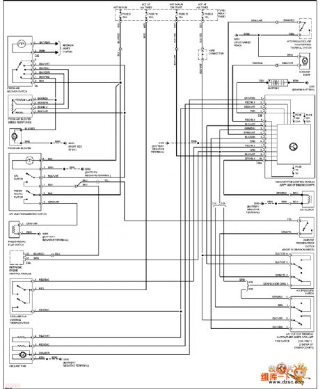
The Volkswagon air-conditioner circuit
Published:2011/6/30 20:37:00 Author:qqtang | Keyword: Volkswagon, air-conditioner
View full Circuit Diagram | Comments | Reading(451)
The same line automatic recording attached device circuit
Published:2011/6/29 2:45:00 Author:Fiona | Keyword: The same line, automatic recording

The same line automatic recording attached device circuit is shown as below, the same line automatic recording attached device can be easily used at different types of domestic and international recording telephone and answering machine.Due to be limited by the original machine power and the original machine volume,it is best to choose small sensitive relay, such as the Nissan SV-5 and M4-5.The device is best to be added at automatic recording tape telephone,modification effect is not obvious on IC language chip type recording telephone.
(View)
View full Circuit Diagram | Comments | Reading(612)
IR4010 internal schematic box circuit
Published:2011/6/30 11:23:00 Author:John | Keyword: schematic box

The figure shows the IR4010 internal schematic box circuit, which indicates the internal circuit components of IR4010 device. It should be noted that it provides the VCC (voltage input response) with over or under voltage protection. When the VCC is equal to16 V, the control circuit starts to work with 6 V lag lock function. It refers that the circuit does not work with under-voltage protection when the VCC is less than (including) 10V. When the VCC is larger than 22V, the circuit does not work the either but with over-voltage protection.
Comparator COMP1 controls the on-and off of the MOSFET. When the VTH (1) is larger than (including).7 V, turn off the MOSFET. Comparator COMP2 controls the connection of the MOSFET. When VTH (2) is less than (including) 1.45 V, the MOSFET is connected.
(View)
View full Circuit Diagram | Comments | Reading(804)
The Guangzhou Honda fixed speed cruise control circuit
Published:2011/6/30 20:33:00 Author:qqtang | Keyword: Guangzhou Honda, fixed speed, cruise control circuit
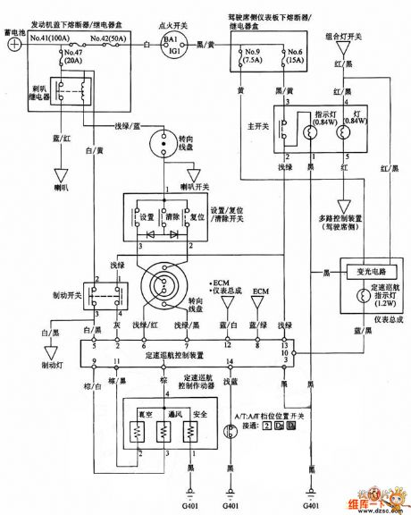
The Guangzhou Honda fixed speed cruise control circuit is shown in the circuit.
(View)
View full Circuit Diagram | Comments | Reading(617)
The self-made temporary 220V inverting power supply circuit
Published:2011/6/30 4:28:00 Author:Seven | Keyword: self-made, inverting, power supply

1. The principle of the circuit The transistor V, the N1 and N2 coils of transformer T and the capacitor C compose the LC oscillating circuit of transformer coupling. The potentiometer RP and resistor R provide bias current for the oscillator. 2. Element selection V is adopted with 3DD59A, R is a 1/4W general resistor, C is 0.22μF/50V, the transformer is self-made, N1 and N2 are the 0.9mm covered wire, N3 is the 0.67mm covered wire, the coil frame can be made of the 1mm hard paper board, the core would better be ferrite of U or loop shape, if not, it can be replaced by silicon-steel sheet of E or F shape.
(View)
View full Circuit Diagram | Comments | Reading(772)
The simple constant temperature control circuit
Published:2011/6/30 20:31:00 Author:qqtang | Keyword: constant temperature, control circuit
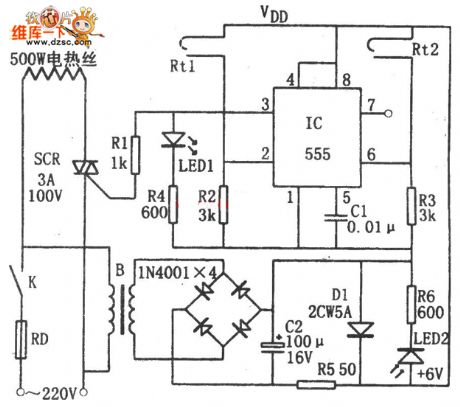
In the figure is the simple constant temperature control circuit, this controller consists of the step-down rectifier circuit, temperature sensor and RS trigger control circuit and so on. The step-down rectifier circuit power supply circuit outputs the +6v voltage. The temperature sensors of Rt1 and Rt2 is modified from a sun light lamp starter, of which Rt1 controls the lower limit value while Rt2 controls the upper limit value of the temperature, and the thermometer is used to adjust the interval. When the power is on, due to the LEV on 5-pin and 6-pin but the high LEV of 3-pin, the dual-way SCR is triggered and conducting.
(View)
View full Circuit Diagram | Comments | Reading(2393)
MAX2003A quick charger practical circuit
Published:2011/6/30 11:11:00 Author:John | Keyword: quick charger

MAX2003A is the NiCad / NiMH battery’s quick charger controller circuit produced by a U.S. company. It can realize automation for the Ni-Cd / Ni-MH battery charging process and ensure the safety, flexibility and reliability of the whole charging process. MAX2003A quick charger practical circuit is shown.
(View)
View full Circuit Diagram | Comments | Reading(1578)
| Pages:1652/2234 At 2016411642164316441645164616471648164916501651165216531654165516561657165816591660Under 20 |
Circuit Categories
power supply circuit
Amplifier Circuit
Basic Circuit
LED and Light Circuit
Sensor Circuit
Signal Processing
Electrical Equipment Circuit
Control Circuit
Remote Control Circuit
A/D-D/A Converter Circuit
Audio Circuit
Measuring and Test Circuit
Communication Circuit
Computer-Related Circuit
555 Circuit
Automotive Circuit
Repairing Circuit
