
Circuit Diagram
Index 1649
555 fridge compressor work timer circuit
Published:2011/6/16 2:53:00 Author:TaoXi | Keyword: fridge, 555, compressor, work, timer
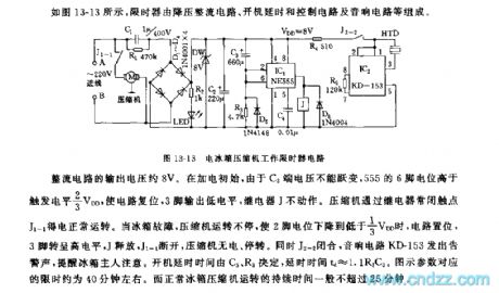
As the figure 13-13 shows, the displayer is composed of the step-down rectifier circuit, the boot delay and control circuit and the audio circuit.etc.
The output voltage of the rectifier circuit is about 8V, at beginning, because the voltage of C3 can not be changed, so the electric potential of 555's pin-6 is higher than the trigger electrical level 2/3VDD to reset the circuit, the pin-3 outputs the low electrical level, the relay J will not work. The compressor gets power through the relay normally closed contact point J1-1 to work. When the fridge is broken, the compressor will not stop working, when the electric potential of pin-2 is lower than 1/3VDD, the circuit sets, pin-3 has the high electrical level, J releases, J1-1 cuts off, so the compressor has no power and stops working.
(View)
View full Circuit Diagram | Comments | Reading(754)
555 fridge electricity saving protector circuit
Published:2011/6/16 3:17:00 Author:TaoXi | Keyword: 555, fridge, electricity saving, protector

As the figure 13-4 shows, the electricity saving protector is composed of the voltage identification circuit, the astable oscillator circuit and the SCR control circuit, the step-down rectifier circuit.
The voltage identification circuit is composed of the potential-divider network and the IC1.etc. The astable multivibrator is composed of the IC2 and R3, RP3, R4, C2, the oscillation frequency depends on the charge and discharge time constant.
The working principle of the electricity saving is: when the voltage of city electricity is normal, the VT2 is in the open circuit state, so the oscillation frequency of the multivibrator IC2 can be adjusted by the potentiometer RP3. When the voltage of city electricity is lower than the refrigerator normal work voltage 175V, the circuit IC1 turns, pin-3 outputs the high electrical level to conduct the VT2.
(View)
View full Circuit Diagram | Comments | Reading(495)
555 large roller-type washing machine electric controller circuit
Published:2011/6/16 3:36:00 Author:TaoXi | Keyword: 555, large roller-type, washing machine, electric controller

As the figure 13-18 shows, the electric controller is composed of the pulse generator, the counter and the relay controller.etc, it has the same functions with the mechanical contact point type controller.
The astable multivibrator is composed of the IC1 and R2, R1, C1, the oscillation period T=0.693(R1+R2)C1. IC2 uses the decimal counter / pulse distributor CD4017, it can be used as the output pulse clock of the IC1, and the ports Y0-Y9 continuously outputs the high level which has the same cycle with the count pulse respectively, the Y0, Y4, Y5 and Y9 successively control the VT1,VT2 and VT3, they start the J1,J2 and J3 to control the contactors 1C and 2C.
(View)
View full Circuit Diagram | Comments | Reading(1003)
555 fridge door-closing reminder circuit (2)
Published:2011/6/16 6:20:00 Author:TaoXi | Keyword: 555, fridge, door-closing, reminder
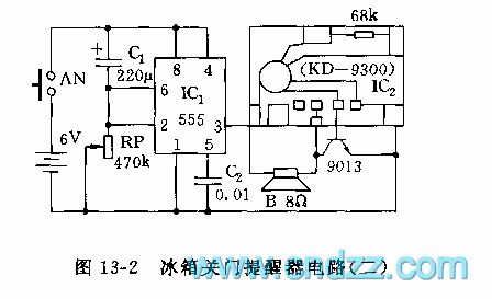
As the figure 13-2 shows, the reminder is composed of the monostable delay circuit which is composed of the 555, C1, RP and a KD-9300 music IC2. When you open the door, the switch AN is pressed, the 6V power adds to the 555, because the voltage of capacitor C1 can not be changed, so pin-2 has the high electric potential to make the 555 to output the low electrical level. After the delay time of 0 to 2 minutes, the circuit sets, IC2 gets the power to send out the sound of music. After you close the door, AN is unclinched, you can change the delay time by adjusting RP.
(View)
View full Circuit Diagram | Comments | Reading(549)
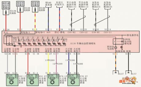
Shanghai Buick Royaum V63.6L car TCS/BAS/ESP circuit diagram
Published:2011/6/24 4:17:00 Author:Nicole | Keyword: Shanghai Buick Royaum, car
View full Circuit Diagram | Comments | Reading(1077)
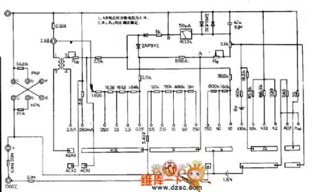
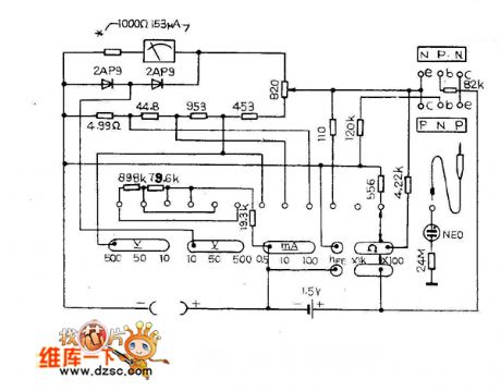
MF77 multimeter circuit diagram
Published:2011/6/24 4:37:00 Author:Nicole | Keyword: multimeter

View full Circuit Diagram | Comments | Reading(1072)
555 trigger and long time delay circuit
Published:2011/6/12 10:58:00 Author:nelly | Keyword: trigger, long time delay
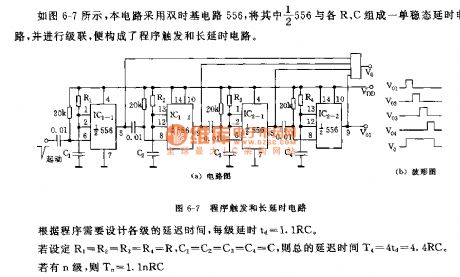
As shown on the figure 6-7, this circuit adopts the dual time base circuit 556. The half of the 556 and R,C make up of a monostable delay circuit and putting it to cascade. Then the trigger and long time delay circuit will be constructed. According to the program, we need to design the every delay time: td=1.1RC. If R1=R2=R3=R4=R, C1=C2=C3=C4=C, the total delay time: T4=4td=4.4RC. If it has n grades, Tn=1.1nRC.
(View)
View full Circuit Diagram | Comments | Reading(1246)
Shanghai Buick Royaum V63.6L car TCS/BAS circuit diagram(1)
Published:2011/6/24 4:15:00 Author:Nicole | Keyword: Shanghai Buick Royaum, car
View full Circuit Diagram | Comments | Reading(475)
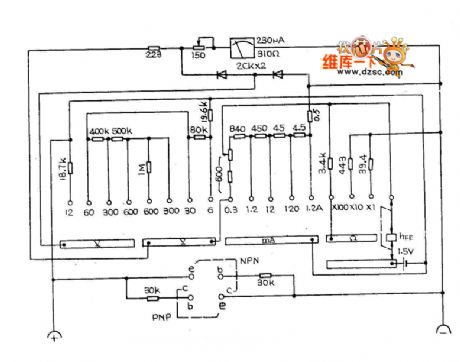
MF78 multimeter circuit diagram
Published:2011/6/24 4:41:00 Author:Nicole | Keyword: multimeter
View full Circuit Diagram | Comments | Reading(782)
MF79 multimeter circuit diagram
Published:2011/6/24 4:41:00 Author:Nicole | Keyword: multimeter

View full Circuit Diagram | Comments | Reading(866)
555 Sine wave Generator Circuit
Published:2011/6/23 22:39:00 Author:Zoey | Keyword: 555sine wave, generator, circuit
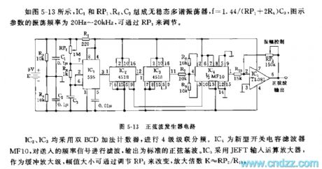
As shown in the figure 5-13, the astable multivibrator is composed of IC1, Rp1, R6 and C3, and f=1.44/(RP1+2R5)C3. Oscillation frequency of the parameter in the figure is 20Hz~20khz, which can be adjusted by RP1.
Figure5-13 Sina wave Generator Circuit
Both IC2 and IC3 use Double BCD up counter for obtain four-stage cascaded frequency. IC4 is a new switched-capacitor filter, it filters the frequency signal sent and output standard sine fundamental. While IC5 uses JEFT to input theoperational amplifier, which is used to butter the amplifier stage, and the value of amplitude can be adjusted by RP2, the magnification K≈RP2/RHo. (View)
View full Circuit Diagram | Comments | Reading(2565)
MF81 multimeter circuit diagram
Published:2011/6/24 4:40:00 Author:Nicole | Keyword: multimeter
View full Circuit Diagram | Comments | Reading(621)
MF82 multimeter circuit diagram
Published:2011/6/24 4:40:00 Author:Nicole | Keyword: multimeter

View full Circuit Diagram | Comments | Reading(965)
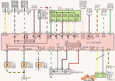
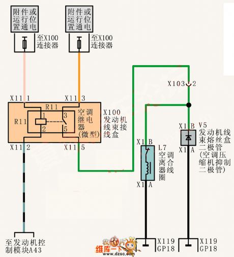
Shanghai Buick Royaum V63.6L car air conditioning system circuit diagram(1)
Published:2011/6/24 4:20:00 Author:Nicole | Keyword: Shanghai Buick Royaum, car, air conditioning system
View full Circuit Diagram | Comments | Reading(481)
Shanghai Buick Royaum V63.6L car air conditioning system circuit diagram(2)
Published:2011/6/24 4:22:00 Author:Nicole | Keyword: Shanghai Buick Royaum, car, air conditioning system
View full Circuit Diagram | Comments | Reading(442)
MF75 multimeter circuit diagram
Published:2011/6/24 4:42:00 Author:Nicole | Keyword: multimeter
View full Circuit Diagram | Comments | Reading(693)
Crystal oscillator Circuit composed of 555
Published:2011/6/23 21:48:00 Author:Zoey | Keyword: Crystal oscillator, Circuit, composed of 555
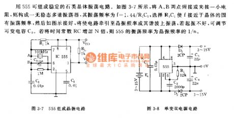
With the composition of a 555 circuit, a quartz crystal oscillator circuit can be formed. As shown in the figure 3-7, after jointing point A and point B or clamping and jointing a small resistance, an astable multi-vibrator is formed and its oscillation frequency f is 1.44/R1C1. Choose a fixed R1C1 oscillation frequency close to f, and then joint the different parts as shown in the picture, tract the circuit to crystal oscillator or to its oscillator on the harmonic. If it does not starts-up well, we can adjust the variable capacitor. If the time constant is multiplied N times, the oscillator frequency will turn to be 1/N of the crystal oscillator frequency.
(View)
View full Circuit Diagram | Comments | Reading(2958)
Optical remote control power switch circuit
Published:2011/6/28 0:12:00 Author:Fiona | Keyword: Optical remote control, power switch

It is a light-controlled power remote control equipment,it can be used for the light of the torch triggering.The circuit consists of two parts:one is the light control circuit;the other one is controlled circuit.The light-controlled part consists of the photoelectric transistor VT1,transistor potentiometer RP and phase transistor VT2.The controlled part consists of the transistor VT3 and the relay KM.When the key switch SB is pressed,the both ends of the voltage-regulator diode vD5 obtains the l 2V DC voltage.The light-emitting diode VD6 displays work.Resistor Rl provides bleeder current loop to the capacitor C1.vD7 is the protection diode.
(View)
View full Circuit Diagram | Comments | Reading(1029)
Motor protector 1
Published:2011/6/27 4:44:00 Author:Nicole | Keyword: Motor, protector
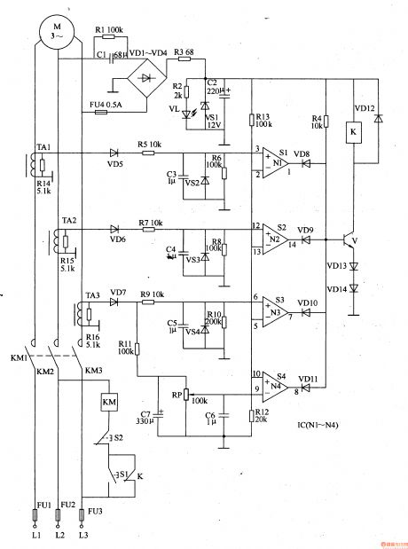
The power supply circuit is composed of capacitors C1, C2, resistors R1-R3, rectifier diodes VD1-VD4, Zener diode VS1 and power supply indication LED VL.
The current detection circuit is made of current transformer TAl-TA3, resistors R5-R11, R14-R16, diodes VD5-VD7, Zener diode VS2-VS4, potentiometer RP, capacitors C3-C7.
The protection control circuit consists of operation amplifier integrated circuit IC(N1-N4), resistors R4, R12, R13, diodes VD8-VDl4, transistor V, relay K, AC contactor KM and starting button S1, stopping button S2.
(View)
View full Circuit Diagram | Comments | Reading(666)
555 Photosensitive oscillator circuit
Published:2011/6/27 3:08:00 Author:Zoey | Keyword: 555 Photosensitive oscillator, circuit
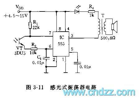
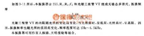
As shown in picture 3-11, this oscillator constitutes an astable multi-vibrator along with a 555, R1, R3, C1 and a photosensitive audion, and its oscillation frequency can be calculated by this formula:
f=1.44/(R+2RVT+2R3)C1
The internal resistance in photosensitive audion VT changes as light change. When exposed in a strong light, is will have a low resistance, vice versa. Therefore, the oscillation frequency changes as sensitivity of light changes, oscillation frequency can change from 1Hz to 6.5Hz.
This oscillator can be used as the leader to explore the way for the blind people, or as the harbinger of dawn or can be used in other situations. (View)
View full Circuit Diagram | Comments | Reading(709)
| Pages:1649/2234 At 2016411642164316441645164616471648164916501651165216531654165516561657165816591660Under 20 |
Circuit Categories
power supply circuit
Amplifier Circuit
Basic Circuit
LED and Light Circuit
Sensor Circuit
Signal Processing
Electrical Equipment Circuit
Control Circuit
Remote Control Circuit
A/D-D/A Converter Circuit
Audio Circuit
Measuring and Test Circuit
Communication Circuit
Computer-Related Circuit
555 Circuit
Automotive Circuit
Repairing Circuit