Control Circuit
555 fridge electricity saving protector circuit
Published:2011/6/16 3:17:00 Author:TaoXi | Keyword: 555, fridge, electricity saving, protector | From:SeekIC

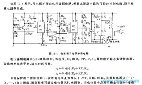
As the figure 13-4 shows, the electricity saving protector is composed of the voltage identification circuit, the astable oscillator circuit and the SCR control circuit, the step-down rectifier circuit.
The voltage identification circuit is composed of the potential-divider network and the IC1.etc. The astable multivibrator is composed of the IC2 and R3, RP3, R4, C2, the oscillation frequency depends on the charge and discharge time constant.
The working principle of the electricity saving is: when the voltage of city electricity is normal, the VT2 is in the open circuit state, so the oscillation frequency of the multivibrator IC2 can be adjusted by the potentiometer RP3. When the voltage of city electricity is lower than the refrigerator normal work voltage 175V, the circuit IC1 turns, pin-3 outputs the high electrical level to conduct the VT2.
Reprinted Url Of This Article:
http://www.seekic.com/circuit_diagram/Control_Circuit/555_fridge_electricity_saving_protector_circuit.html
Print this Page | Comments | Reading(3)

Article Categories
power supply circuit
Amplifier Circuit
Basic Circuit
LED and Light Circuit
Sensor Circuit
Signal Processing
Electrical Equipment Circuit
Control Circuit
Remote Control Circuit
A/D-D/A Converter Circuit
Audio Circuit
Measuring and Test Circuit
Communication Circuit
Computer-Related Circuit
555 Circuit
Automotive Circuit
Repairing Circuit
Code: