555 Circuit
555 Sine wave Generator Circuit
Published:2011/6/23 22:39:00 Author:Zoey | Keyword: 555sine wave, generator, circuit | From:SeekIC

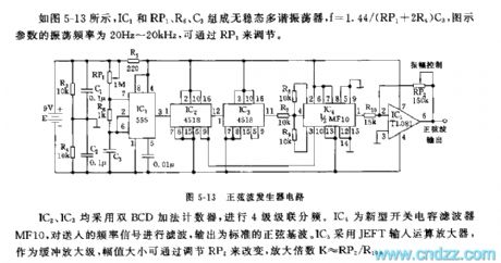
As shown in the figure 5-13, the astable multivibrator is composed of IC1, Rp1, R6 and C3, and f=1.44/(RP1+2R5)C3. Oscillation frequency of the parameter in the figure is 20Hz~20khz, which can be adjusted by RP1.
Figure5-13 Sina wave Generator Circuit
Both IC2 and IC3 use Double BCD up counter for obtain four-stage cascaded frequency. IC4 is a new switched-capacitor filter, it filters the frequency signal sent and output standard sine fundamental. While IC5 uses JEFT to input theoperational amplifier, which is used to butter the amplifier stage, and the value of amplitude can be adjusted by RP2, the magnification K≈RP2/RHo.
Reprinted Url Of This Article:
http://www.seekic.com/circuit_diagram/555_Circuit/555_Sine_wave_Generator_Circuit.html
Print this Page | Comments | Reading(3)

Article Categories
power supply circuit
Amplifier Circuit
Basic Circuit
LED and Light Circuit
Sensor Circuit
Signal Processing
Electrical Equipment Circuit
Control Circuit
Remote Control Circuit
A/D-D/A Converter Circuit
Audio Circuit
Measuring and Test Circuit
Communication Circuit
Computer-Related Circuit
555 Circuit
Automotive Circuit
Repairing Circuit
Code: