Signal Processing
555 fridge compressor work timer circuit
Published:2011/6/16 2:53:00 Author:TaoXi | Keyword: fridge, 555, compressor, work, timer | From:SeekIC

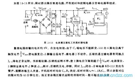
As the figure 13-13 shows, the displayer is composed of the step-down rectifier circuit, the boot delay and control circuit and the audio circuit.etc.
The output voltage of the rectifier circuit is about 8V, at beginning, because the voltage of C3 can not be changed, so the electric potential of 555's pin-6 is higher than the trigger electrical level 2/3VDD to reset the circuit, the pin-3 outputs the low electrical level, the relay J will not work. The compressor gets power through the relay normally closed contact point J1-1 to work. When the fridge is broken, the compressor will not stop working, when the electric potential of pin-2 is lower than 1/3VDD, the circuit sets, pin-3 has the high electrical level, J releases, J1-1 cuts off, so the compressor has no power and stops working.
Reprinted Url Of This Article:
http://www.seekic.com/circuit_diagram/Signal_Processing/555_fridge_compressor_work_timer_circuit.html
Print this Page | Comments | Reading(3)

Article Categories
power supply circuit
Amplifier Circuit
Basic Circuit
LED and Light Circuit
Sensor Circuit
Signal Processing
Electrical Equipment Circuit
Control Circuit
Remote Control Circuit
A/D-D/A Converter Circuit
Audio Circuit
Measuring and Test Circuit
Communication Circuit
Computer-Related Circuit
555 Circuit
Automotive Circuit
Repairing Circuit
Code: