Circuit Diagram
Index 1653
automatic motor starting circuit with Doppler-effect sensor RD9481
Published:2011/6/30 11:06:00 Author:John | Keyword: Doppler-effect sensor, motor
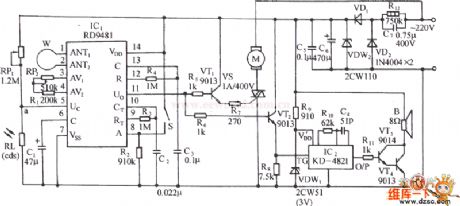
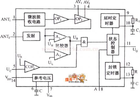
The circuit is just as shown. It includes the Doppler -effect sensor control circuit, thyristor control circuit, music sound output circuit, large circuit and AC buck rectifier circuit and so on. Doppler-effect sensor IC RD9481 is the core device of the circuit, whose internal functional block circuit is also shown.
(View)
View full Circuit Diagram | Comments | Reading(1157)
The vehicle loudspeaker circuit
Published:2011/6/30 5:02:00 Author:Seven | Keyword: vehicle loudspeaker

In the figure is the vehicle loudspeaker circuit. The left side of the figured dotted line is the loudspeaker circuit of the former car, SI is the key of the loudspeaker on the steering wheel. S2 is the added single-pole double-throw switch, which is used in the shift of the electric loudspeaker and the audio loudspeaker in the former car. The the switch S is at the position of 2 , by pressing the switch SI, the capacitor Cl is charged, the triodes of VT1 and VT2 are conducting, the relay JI is pulling in, and the normally open connector J1-1 is closed and offers power to the circuit for 15s. IC1 is the specialized audio integrated circuit HL-169, whose working time is 2.8s.
(View)
View full Circuit Diagram | Comments | Reading(763)
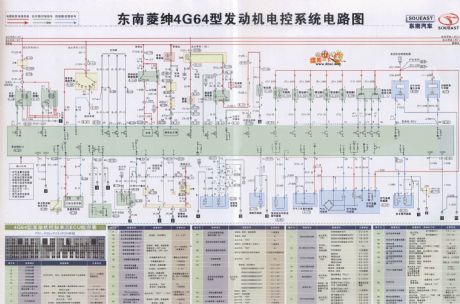
Southeast Soveran 4G64 engine electronic control system circuit
Published:2011/6/30 10:53:00 Author:John | Keyword: engine, electronic control system
View full Circuit Diagram | Comments | Reading(2248)
Piezoelectric high level automatic control and alarming circuit
Published:2011/6/30 10:51:00 Author:John | Keyword: automatic control

The shown circuit consists of the piezoelectric material level sensor, relay control mechanical circuit, analog voice circuit and AC buck rectifier circuit. When the material level rises to the high material level, the circuit can be issued for a given analog sound and also cut off the power supply of the feeding equipment. Then the feeding process stops in order to ensure safe operation. IC1 is a piezoelectric material level sensing circuit, which consists of self-excited oscillator, rectifier circuit, voltage comparator circuit and output stage of the open circuit.
(View)
View full Circuit Diagram | Comments | Reading(793)
MAX1894/MAX1924 typical application circuit without pre-charging function
Published:2011/6/30 10:44:00 Author:John | Keyword: pre-charging function, typical application
View full Circuit Diagram | Comments | Reading(896)
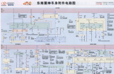
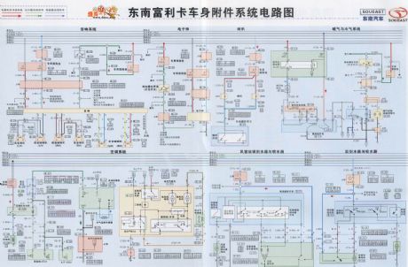
Southeast Soveran body attachment circuit
Published:2011/6/30 10:34:00 Author:John | Keyword: body attachment
View full Circuit Diagram | Comments | Reading(606)
The RC trigger single-way thyristor dimmer circuit
Published:2011/6/30 3:54:00 Author:Seven | Keyword: RC trigger, single-way thyristor, dimmer

In the figure is the single-way thyristor dimmer circuit whose trigger circuit is composed of RC elements, the 220v AC is rectified by VD1~VD4 and becomes a DC impulse voltage, and then it is added between the positive pole and passive pole of the thyristor VT. RP, R and C2 compose the trigger circuit, the DC pulse voltage is charging C2 through RP and R, when it reaches a certain value, the thyristor VT is open and the bulb E is glowing because of getting power. When the impulse voltage between the two poles of of VT is over zero, VT is broken down automatically, and the power supply charges C2 through RP and R again.
(View)
View full Circuit Diagram | Comments | Reading(3650)
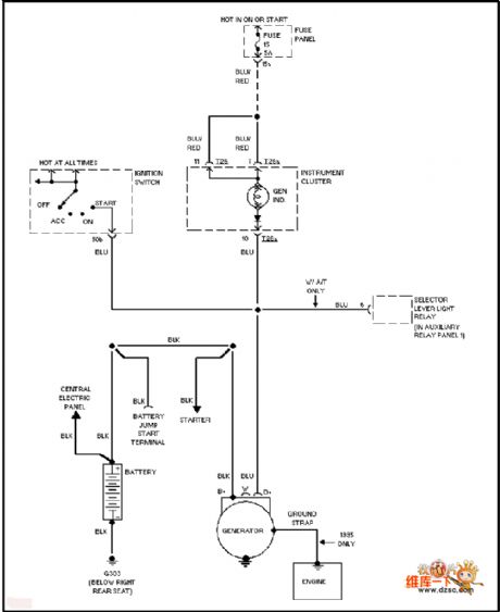
Audi charging system circuit
Published:2011/6/30 10:32:00 Author:John | Keyword: charging system
View full Circuit Diagram | Comments | Reading(869)
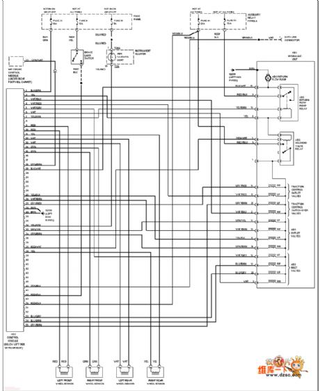
Audi (front drive) anti-lock braking circuit
Published:2011/6/30 10:34:00 Author:John | Keyword: anti-lock
View full Circuit Diagram | Comments | Reading(625)
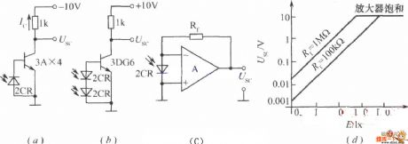
Optical linear detection circuit
Published:2011/6/30 10:33:00 Author:John | Keyword: linear detection
View full Circuit Diagram | Comments | Reading(431)
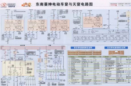
Southeast Soveran power window and sunroof window circuit
Published:2011/6/30 10:32:00 Author:John | Keyword: power window, sunroof window
View full Circuit Diagram | Comments | Reading(685)
The auto open/close curtain controller circuit
Published:2011/6/30 3:31:00 Author:Seven | Keyword: curtain controller
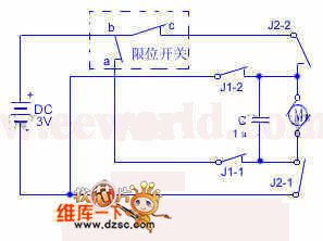
This controller can recognize the brightness in the room automatically, which can control the curtain and make the natural light in the optimum state. In figure 1, the LDR RD and the time-based circuit 5G1555 compose the brightness recognition sector. The LDR RD receives the natural light and its resistance changes, which is set as RD1, at the moment, RD1 is falling down. The elements and their parameters are shown as follows: BG1:3DG12,BG2:3CG14,BG3:3DG12,BG4:3DG12B。D1~D3:2CP,D4~D7:2CP14,DW:2CW22C/100mA/7.5V。W1、W2:100K,RD:the LDR of the 625 type.
(View)
View full Circuit Diagram | Comments | Reading(1505)
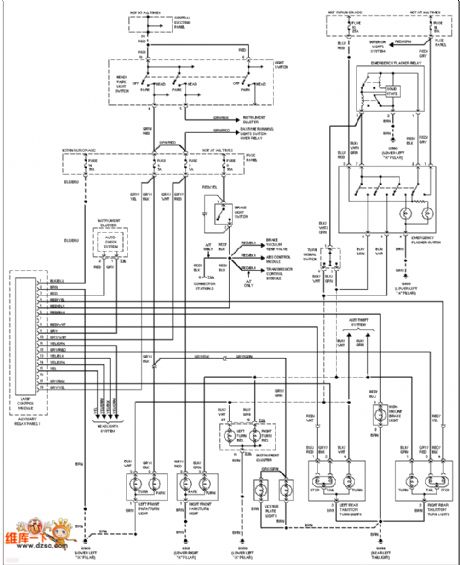
Audi gated light basic circuit
Published:2011/6/30 10:30:00 Author:John | Keyword: gated light
View full Circuit Diagram | Comments | Reading(671)
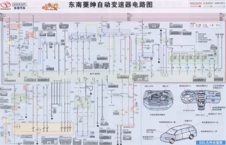
Southeast Soveran automatic transmission circuit
Published:2011/6/30 10:29:00 Author:John | Keyword: automatic transmission
View full Circuit Diagram | Comments | Reading(626)
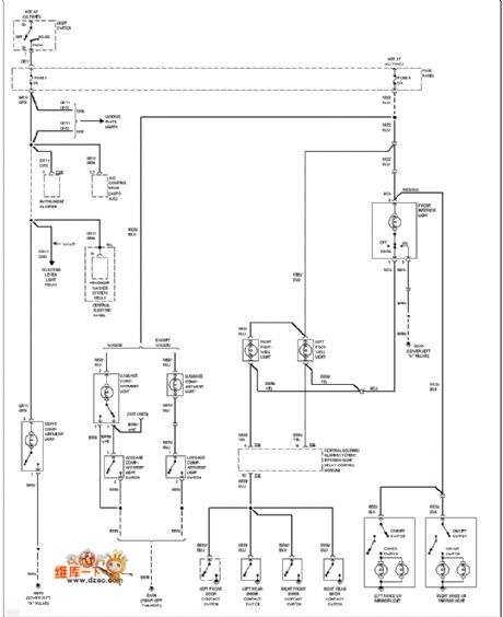
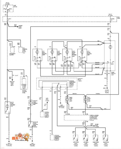
Audi interior light circuit
Published:2011/6/30 10:28:00 Author:John | Keyword: interior light
View full Circuit Diagram | Comments | Reading(743)
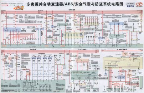
Southeast Lioncel automatic transmission, ABS, airbag and anti-theft system schematic
Published:2011/6/30 10:28:00 Author:John | Keyword: automatic transmission, ABS, airbag, anti-theft system
View full Circuit Diagram | Comments | Reading(1032)
The self-made fast hand drier circuit
Published:2011/6/30 3:43:00 Author:Seven | Keyword: fast hand drier

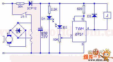
45. The self-made fast hand drier circuitThe drier will blow out warm air if the washed hand is below it, and when the hand becomes dry, it will stop automatically, see as figure 2. When there is light, the 1-pin of the IC is in a low LEV, TWH8751 is blocked, J is power-off, J1-1 is broken down. When the hand is blocking the light, D2 is in a high resistance, the 2-pin of IC is in a low LEV, so the output terminal of IC is conducting, J1-1 is passable, the heating wire and motor get power, so the warm air is blown out. The power supply of the control wire is stepped down and rectified by the 36K resistor and 2CP12, then the voltage of 18V or so is acquired.
(View)
View full Circuit Diagram | Comments | Reading(565)
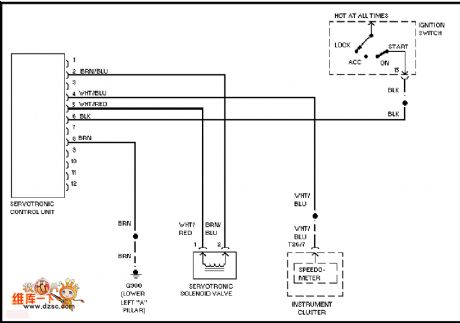
Audi electronic power steering circuit
Published:2011/6/30 10:26:00 Author:John
View full Circuit Diagram | Comments | Reading(2063)
Audi (with DRL) fog lamp circuit
Published:2011/6/30 10:25:00 Author:John | Keyword: fog lamp
View full Circuit Diagram | Comments | Reading(752)
Southeast Freeca body attachment system circuit
Published:2011/6/30 10:24:00 Author:John | Keyword: body, attachment system
View full Circuit Diagram | Comments | Reading(682)
| Pages:1653/2234 At 2016411642164316441645164616471648164916501651165216531654165516561657165816591660Under 20 |
Circuit Categories
power supply circuit
Amplifier Circuit
Basic Circuit
LED and Light Circuit
Sensor Circuit
Signal Processing
Electrical Equipment Circuit
Control Circuit
Remote Control Circuit
A/D-D/A Converter Circuit
Audio Circuit
Measuring and Test Circuit
Communication Circuit
Computer-Related Circuit
555 Circuit
Automotive Circuit
Repairing Circuit
