Circuit Diagram
Index 1655
LA1185 audio IC circuit
Published:2011/6/30 19:28:00 Author:TaoXi | Keyword: audio, IC

The LA1185 audio IC circuit is as shown in the figure:
(View)
View full Circuit Diagram | Comments | Reading(3219)
Vizi saloon car fan, warm wind and air conditioning circuits
Published:2011/6/30 19:33:00 Author:TaoXi | Keyword: Vizi, saloon car, fan, warm wind, air conditioning
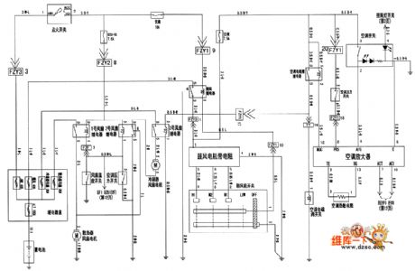
The Vizi saloon car fan, warm wind and air conditioning circuits:
(View)
View full Circuit Diagram | Comments | Reading(452)
LA1186N audio IC circuit
Published:2011/6/30 19:29:00 Author:TaoXi | Keyword: audio, IC

The LA1186N audio IC circuit is as shown in the figure:
(View)
View full Circuit Diagram | Comments | Reading(2199)
The Guangzhou-Honda instrument system circuit
Published:2011/6/30 20:20:00 Author:qqtang | Keyword: Guangzhou-Honda, instrument system
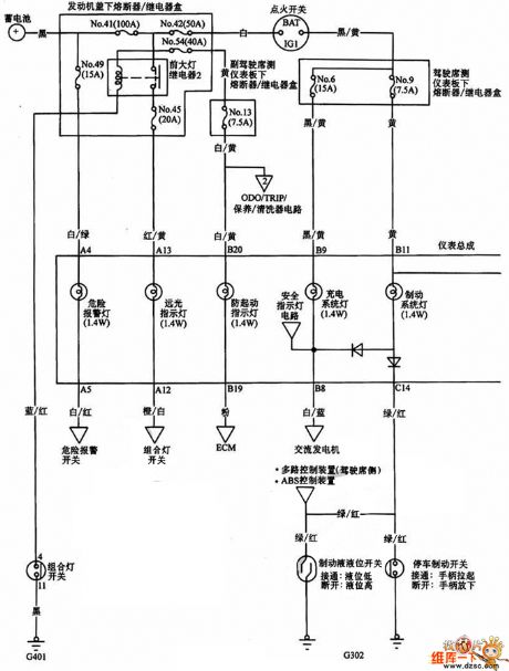
The Guangzhou-Honda instrument system circuit is shown in the figure.
(View)
View full Circuit Diagram | Comments | Reading(401)
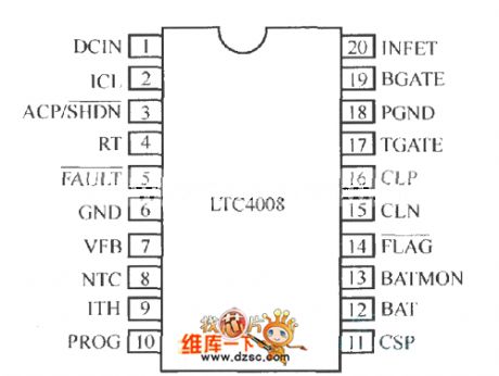
LTC4008 internal structure and external components connection circuit
Published:2011/6/30 19:38:00 Author:TaoXi | Keyword: internal structure, external components, connection circuit
View full Circuit Diagram | Comments | Reading(464)
LA1260 audio IC circuit
Published:2011/6/30 19:30:00 Author:TaoXi | Keyword: audio, IC

The LA1260 audio IC circuit is as shown in the figure:
(View)
View full Circuit Diagram | Comments | Reading(5369)
AC voltage level circuit
Published:2011/6/30 19:47:00 Author:TaoXi | Keyword: AC, voltage level
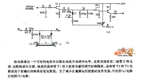
This circuit automatically or manually adjusts the level through a variable capacitor bleeder. Here the bleeder is composed of the varactor D, the capacitance and the resistance. The field effect transistor T1 can be used in the isolation between the signal source and the adjusting loop. The transistor T2 and T3 can be used to make the output circuit to has low resistance value. In order to reduce the waveform distortion when the high-frequency voltage is high, you can connect the circuit of figure (b) after the circuit of figure (a).
(View)
View full Circuit Diagram | Comments | Reading(471)
The constant temperature control circuit of the developing solution
Published:2011/6/30 20:19:00 Author:qqtang | Keyword: temperature control circuit, developing solution
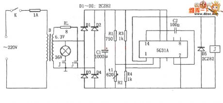
In the figure is the constant temperature control circuit of the developing solution. This circuit consists of the step-down rectifier power supply circuit(B, D1~D4, C1 and so on), temperature detecting bridge R3~R4, voltage comparing amplifier and power output circuit 5G31, relay J, load RL and so on, of which R3 has the same resistance with R4, and they are linked to the passive input terminal as the Vref. R2 is a thermistor, R1 is the temperature adjusting resistor, RL is the loading resistor(heater) and 5G31 is the audio power amplifier.When the power is on, the temperature is low and the resistance of R1 is high.
(View)
View full Circuit Diagram | Comments | Reading(877)
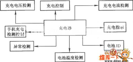
General mobile phone battery charger circuit
Published:2011/6/30 19:50:00 Author:TaoXi | Keyword: General, mobile phone, battery, charger
View full Circuit Diagram | Comments | Reading(1222)
LA1265 audio IC circuit
Published:2011/6/30 19:31:00 Author:TaoXi | Keyword: audio, IC

The LA1265 audio IC circuit is as shown in the figure:
(View)
View full Circuit Diagram | Comments | Reading(4221)
Vizi saloon car quartz clock, radio-cassette player and rear window defrosting circuits
Published:2011/6/30 19:35:00 Author:TaoXi | Keyword: Vizi, saloon car, quartz clock, radio-cassette player, rear window, defrosting circuits
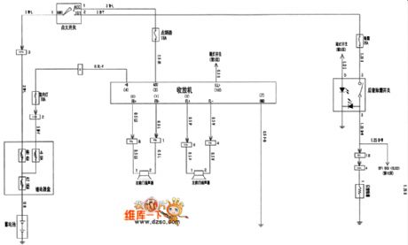
The Vizi saloon car quartz clock, radio-cassette player and rear window defrosting circuits:
(View)
View full Circuit Diagram | Comments | Reading(590)
Potential isolated current measurement circuit
Published:2011/6/30 20:00:00 Author:TaoXi | Keyword: Potential, isolated, current measurement
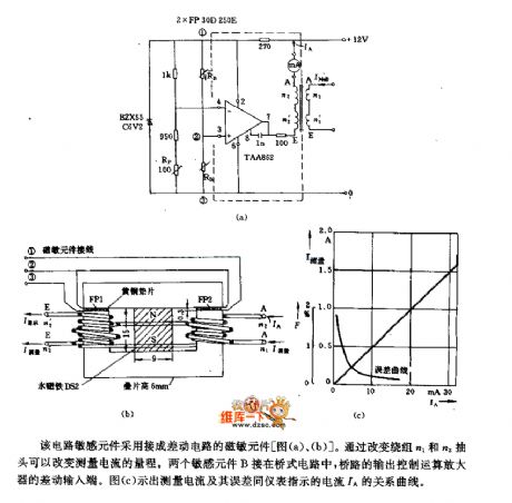
This circuit sensitive component is connected into the magnetic susceptibility component of the differential circuit. By changing the taps of winding n1 and winding n2, you can change the measuring range of the measuring current. The two sensitive components B are connected in the bridge type circuit, the output of the bridge type circuit controls the differential input port of the operational amplifier. Figure (c) shows the relation curve between the measuring current and the measurement error meter indicating current IA.
(View)
View full Circuit Diagram | Comments | Reading(776)
Smart phone charger module circuit
Published:2011/6/30 20:02:00 Author:TaoXi | Keyword: Smart phone, charger, module circuit
View full Circuit Diagram | Comments | Reading(491)
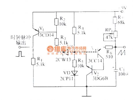
Low frequency adjustment circuit
Published:2011/6/30 20:16:00 Author:TaoXi | Keyword: Low frequency, adjustment circuit

The output port of this circuit is connected with the output jack of the wobbling frequency signal generator, the wobbling frequency signal is rectified and adds to the Mosfet T1. The PNP transistor T2 adjusts the operating point through the potentiometer RP, the output signal is led to the final stage transistor through the transistor T3. The output signal of the final stage transistor's collector adjusts the low frequency oscillator's anode voltage with correct polarity.
(View)
View full Circuit Diagram | Comments | Reading(582)
The electric switch circuit of touch type (5)
Published:2011/6/30 5:27:00 Author:Seven | Keyword: electric switch, touch type
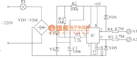
The electric switch circuit of touch type in the following introduction is in 2-line connection, which can easily replace the ordinary mechanical switch. The circuit consists of the time-based integrated circuit IC(NE555), thyristor VT, rectifying diodes VD1 and VD4, regulated diode VS and so on.
Elements selection. R2 is chosen as the 1/2W carbon film resistor, and the other resistors can be 1/4W carbon film resistor. C1 can be the aluminium electrolytic capacitor with the withstand voltage higher than 16V, C2 can be the ordinary dacron capacitor. All of VD1~VD4 are chosen as the 1N4007 rectifier diode. (View)
View full Circuit Diagram | Comments | Reading(654)
The electric switch circuit of touch type (1)
Published:2011/6/30 5:13:00 Author:Seven | Keyword: electric switch, touch type
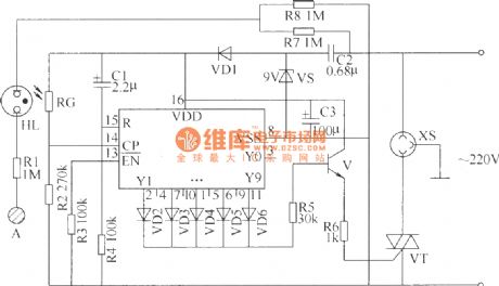
The following is to introduce a switch circuit of touch type which is made of CD4017 digital integrated circuit, thyristors and so on, when the hand touches the control pole, the electric switch will take action (ON or OFF) once, which has the same functions as ordinary mechanical switch, and it can be used to control the lighting lamp, ventilator and so on.This switch circuit consists of the power supply circuit, touching control input circuit, counter circuit and the control executing circuit.
Elements selection:R1~R8 can be chosen as the 1/4W carbon film resistor or metal film resistor. (View)
View full Circuit Diagram | Comments | Reading(561)
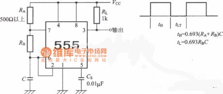
self-excited and multi-harmonic oscillator circuit
Published:2011/6/27 21:25:00 Author:chopper | Keyword: self-excited, multi-harmonic, oscillator circuit
View full Circuit Diagram | Comments | Reading(822)
monotube quartz crystal oscillator circuit
Published:2011/6/27 21:16:00 Author:chopper | Keyword: monotube, quartz crystal, oscillator circuit
View full Circuit Diagram | Comments | Reading(510)
Toshiba 2500XH correction circuit
Published:2011/6/27 21:12:00 Author:chopper | Keyword: Toshiba, correction circuit
View full Circuit Diagram | Comments | Reading(609)
7W audio power amplifier (LF356) circuit
Published:2011/6/22 20:25:00 Author:chopper | Keyword: 7W, audio power, amplifier

(View)
View full Circuit Diagram | Comments | Reading(1914)
| Pages:1655/2234 At 2016411642164316441645164616471648164916501651165216531654165516561657165816591660Under 20 |
Circuit Categories
power supply circuit
Amplifier Circuit
Basic Circuit
LED and Light Circuit
Sensor Circuit
Signal Processing
Electrical Equipment Circuit
Control Circuit
Remote Control Circuit
A/D-D/A Converter Circuit
Audio Circuit
Measuring and Test Circuit
Communication Circuit
Computer-Related Circuit
555 Circuit
Automotive Circuit
Repairing Circuit
