Remote Control Circuit
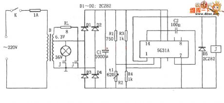
The constant temperature control circuit of the developing solution
Published:2011/6/30 20:19:00 Author:qqtang | Keyword: temperature control circuit, developing solution | From:SeekIC

In the figure is the constant temperature control circuit of the developing solution. This circuit consists of the step-down rectifier power supply circuit(B, D1~D4, C1 and so on), temperature detecting bridge R3~R4, voltage comparing amplifier and power output circuit 5G31, relay J, load RL and so on, of which R3 has the same resistance with R4, and they are linked to the passive input terminal as the Vref. R2 is a thermistor, R1 is the temperature adjusting resistor, RL is the loading resistor(heater) and 5G31 is the audio power amplifier.When the power is on, the temperature is low and the resistance of R1 is high.
Reprinted Url Of This Article:
http://www.seekic.com/circuit_diagram/Remote_Control_Circuit/The_constant_temperature_control_circuit_of_the_developing_solution.html
Print this Page | Comments | Reading(3)

Article Categories
power supply circuit
Amplifier Circuit
Basic Circuit
LED and Light Circuit
Sensor Circuit
Signal Processing
Electrical Equipment Circuit
Control Circuit
Remote Control Circuit
A/D-D/A Converter Circuit
Audio Circuit
Measuring and Test Circuit
Communication Circuit
Computer-Related Circuit
555 Circuit
Automotive Circuit
Repairing Circuit
Code: