
Circuit Diagram
Index 1657
Motor underloading energy saver circuit diagram 1
Published:2011/6/13 5:59:00 Author:Lucas | Keyword: Motor , underloading, energy saver
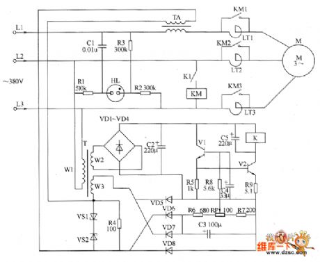
The motor underloading energy saver circuit is composed of the power supply circuit, current sampling circuit, phase sequence indication circuit, control amplifier circuit and other components, and the circuit is shown as the chart. Power supply circuit is composed of the power transformer T, rectifier diodes VD1 ~ VD4 and filter capacitor C2 and so on. Current sampling circuit consists of the current transformer TA, Zener diodes VS1 and VS2, resistor Ⅲ and diodes VD5 ~ VD8 and so on. Phase sequence indicating circuit is composed of the neon light HL, resistors R1 ~ R3, capacitor C1 and so on. Control amplifier circuit consists of the transistors V1 and V2, resistors R5 ~ R9, potentiometer RP, capacitors C4 and C5 and the relay K1 and so on. LT1 ~ LT3 are saturable reactors.
(View)
View full Circuit Diagram | Comments | Reading(1922)
Gas leak alarm circuit diagram
Published:2011/6/13 5:04:00 Author:Lucas | Keyword: Gas leak alarm
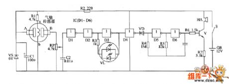
The gas leak alarm circuit is composed of the power supply circuit, gas detection circuit, LED indicating circuit and sound alarm circuit, and the circuit is shown as the chart. Power supply circuit is composed of the battery CB, power switch s, current limiting resistor R2, zener diode VS and filter capacitor C1. Gas detection circuit consists of the gas sensor, resistors R1 and potentiometer RP. LED indicating circuit consists of the NOT gates D1~D2 which are inside of NOT gate integrated circuit IC1(D1~D6), resistor R3, capacitor C2, and two-color light-emitting diodes VL. Sound alarm circuit is composed of the diode VD, NOT gates D4~D6 which are inside of IC, resistors R4 ~ R7, capacitor C3, transistor V, and buzzer HA. R2 uses 1/2W metal film resistor.
(View)
View full Circuit Diagram | Comments | Reading(1508)
Rural wire broadcasting disconnecting teller circuit diagram
Published:2011/6/13 4:57:00 Author:Lucas | Keyword: Rural, wire broadcasting, disconnecting teller

The rural wire broadcasting disconnecting teller circuit is composed of the carrier launched circuit, carrier receiving circuit, alarm circuit and power supply circuit, and the circuit is shown as the chart. Carrier launched circuit (cable radio lines are installed in the terminal) is composed of the high-frequency oscillator circuit and amplified output circuit. High-frequency oscillator consists of the NOT gates D1, D2 which are inside of NOT gate integrated circuit IC1 (D1 ~ D3), resistor R1, potentiometer RP1 and capacitor C1; Amplified output circuit is composed of the D3 which is inside of IC1, capacitors C2 ~ C6 , transistors V1, V2, resistors R2, R3 and IF transformer T1. R1 ~ R13 use 1/4W metal film resistors or carbon film resistors. RP1 and RP2 use small synthetic membrane potentiometer or variable resistor.
(View)
View full Circuit Diagram | Comments | Reading(615)
Seedling tent seedling growth stimulator circuit diagram
Published:2011/6/14 3:19:00 Author:Lucas | Keyword: Seedling tent, seedling growth stimulator

The seedling tent seedling growth stimulator circuit is composed of the transistors V1, V2, potentiometer RP, capacitors C1, C2, speaker BL, power switch S and battery CB, and the circuit is shown as the chart. V1, V2, and RP, C1 form a simple pulse generator. RP selects a small organic solid potentiometer or variable resistor. C1 chooses the monolithic capacitor or polyester capacitor; C2 selects the aluminium electrolytic capacitor with the voltage in 10V. V1 chooses 3DG6 or 59013 NPN silicon transistor; V2 uses 3AX31, 3AX81 or 3AX83 germanium PNP transistor. BL uses the 0.25W, 8Ω electric speaker. GB selects the 6V small-capacity maintenance-free battery. S uses the monopole tumble switch.
(View)
View full Circuit Diagram | Comments | Reading(948)
Heart Rhythm Tester (the 4th)
Published:2011/6/23 21:40:00 Author:Felicity | Keyword: Heart Rhythm Tester (the 4th)
Work of the circuit
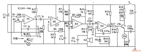
The circuit consists of photo electricity testing circuit, signal amplifying circuit, buzzer driving circuit and current indicating circuit. (It is shows in picture 9-56.)
When you do the test, put your finger between EL and RG. Some lights of EL go through the finger and shines on RG. RG produces sensitive signal. The signal is amplified by N1-N3 and separates into two parts. One drive HA makes the buzzer work. And the other one goes through ammeter and indicates the current value. The current value increases by the rate of heart beating.
Change the value of RP1 to change the accuracy. Change the value of RP2 to change the testing scope. (View)
View full Circuit Diagram | Comments | Reading(650)
Heart Rhythm Tester (the 3rd)
Published:2011/6/23 21:39:00 Author:Felicity | Keyword: Heart Rhythm Tester (the 3rd)
Work of the circuit
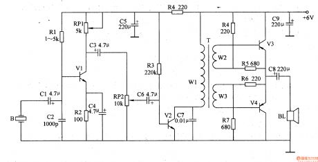
The circuit consists of sensor B, pre-amplifying circuit, low frequency amplifying circuit and capacity amplifying circuit. (It is shows in picture 9-55.)
When you use the tester, put it on the heart area. Use hands to fix it. B changes the sound of hearting beating into electronic signal. The electronic signal is pre-amplified by V1, sound controlled by RP2, low frequency amplified by V2 and capacity amplified by V3, V3. The amplifier BL will play the amplified sound of heart beating. (View)
View full Circuit Diagram | Comments | Reading(554)
Electric Medical Attracting Controlling Circuit (the 3rd)
Published:2011/6/25 5:22:00 Author:Felicity | Keyword: Electric Medical Attracting Controlling Circuit (the 3rd)
Work of the circuit
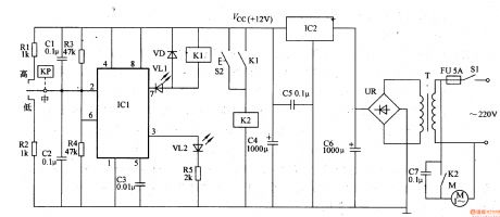
The circuit consists of power circuit, negative pressure testing circuit, bistable state circuit, VL indicating circuit and controlling execution circuit. (It is showed in picture 9-45.)
Turn on the power switch S2. The 220V AC voltage supplies +12V working power to bistable state circuit and controlling execution circuit.
When the circuit just starts working, the gas in the negative pressure bottle is of normal state. The internal outputting circuit of KP is closed and VL1 is lightened. At the same time, M starts working normally. When the negative pressure reaches to a certain value, M stops working. At the same time VL2 is lightened and VL1 is turned off. When the negative pressure is lower than a certain value, M starts working immediately.
S2 is the manual button. Press S1 and M starts working. Relax S2 and M stops working. (View)
View full Circuit Diagram | Comments | Reading(496)
Electric Medical Attracting Controlling Circuit (the 2nd)
Published:2011/6/25 5:20:00 Author:Felicity | Keyword: Electric Medical Attracting Controlling Circuit (the 2nd)
Work of the circuit
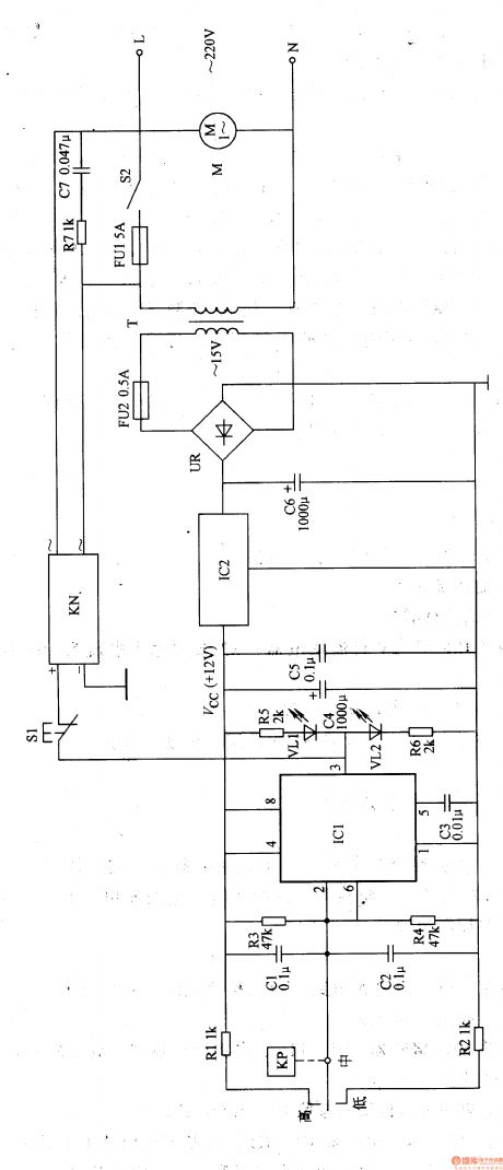
The circuit consists of power circuit, negative pressure testing circuit, bistable state circuit, working condition indicating circuit and controlling execution circuit. (It is showed in picture 9-44.)
Turn on the power switch S2. The 220V AC voltage supplies +12V working power to IC. When S2 is just turned on, the gas in the negative pressure bottle is of normal state. The internal outputting circuit of KP is closed and VL1 is lightened. When the negative pressure reaches to a certain value, M stops working. At the same time VL2 is lightened and VL1 is turned off. S1 is the manual button. Press S1 and M starts working. Relax S1 and M stops working. (View)
View full Circuit Diagram | Comments | Reading(481)
Charger for Motor Vehicle Storage Battery (the 7th)
Published:2011/6/26 9:23:00 Author:Felicity | Keyword: Charger for Motor Vehicle Storage Battery (the 7th)
Work of the circuit
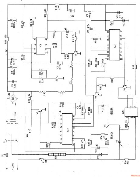
The circuit consists of power circuit, pulse producing circuit and constant current charging circuit. (It is showed in picture 7-152.)
Turn on the power and the 220V AC voltage produces +15V voltage. The voltage is supplied to V and VU through R2 and R5. At the same time, GB begins charging. Change the value of RP2 and RP3 to change the charging current.
If the value of current is larger than the limited value of RP1, the pressure on V4 decreases. So the charging current is limited in a certain range.
Put S1 in the discharging position and S3 in the 50V position. Then turn off S2 and string a load between the poles of GB. At this time, GB is discharging. Put S1 in the charging position and turn on S2. Put S3 in the position of 250V. link the positive pole with the outputting positive pole. link the negative pole with the outputting negative pole. Then connect the 220V AC voltage to make it work. (View)
View full Circuit Diagram | Comments | Reading(906)
Charger for Motor Vehicle Storage Battery (the 6th)
Published:2011/6/26 9:22:00 Author:Felicity | Keyword: Charger for Motor Vehicle Storage Battery (the 6th)
Work of the circuit
The circuit consists of main charging circuit and controlling circuit. (It is showed in picture 7-151.)
Turn on the power switch S. The 220V AC is reduced by T and rectified by UR. It then produces 24V pulse DC voltage. The voltage is added to the collectors of V2 and V3. V3 outputs 20V DC voltage to work as the changing voltage of GB. Change the value of RP to change the working current of V1-V3. In that way we can change the charging current. (View)
View full Circuit Diagram | Comments | Reading(481)
Charger for Motor Vehicle Storage Battery (the 5th)
Published:2011/6/26 9:19:00 Author:Felicity | Keyword: Charger for Motor Vehicle Storage Battery (the 5th)
Work of the circuit
The circuit consists of main charging circuit and controlling circuit. (It is showed in picture 7-150.)
Turn on the battery GB and the diode VL is lightened. At this moment the pressure on GB is rather low (between 8V and 12V). The 220V AC voltage charges GB. When the voltage on GB reaches 15V, V1 is transmitted. And the charging circuit stops charging the battery. When the voltage decreases to 12.5V, the changing begins again. This keeps the voltage on GB at the value of 15V. (View)
View full Circuit Diagram | Comments | Reading(474)
Magnetism Pulse Therapeutic Equipment (the 1st)
Published:2011/6/28 7:48:00 Author:Felicity | Keyword: Magnetism pulse Therapeutic Equipment (the 1st)
Work of the circuit
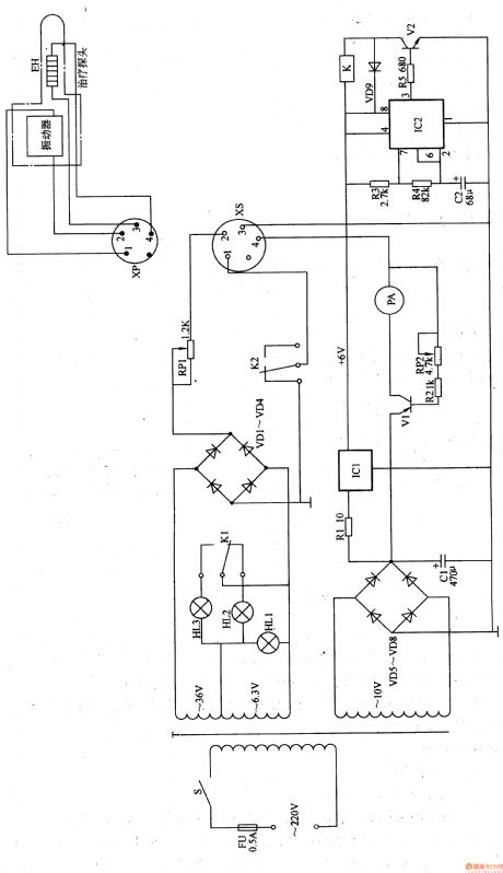
The circuit consists of power circuit, timing circuit, sound indicating circuit, magnetism pulse controlling circuit and heating controlling circuit. (It is showed in picture 9-15.)
Turn on power switch S1. The 220V AC voltage is adjusted and produces +15V voltage. It separates in to two parts. One is supplied to sound indicating circuit and magnetism pulse controlling circuit. While the other one is changed into 9V voltage and IC2 and KN.
The regular time is 60min. turn on the power and EH makes sounds. When the regular time is over, EH stops working and HA makes sound.
When EH is working, the temperature increases as well as the value of RT. When it reaches a certain degree, EH stops working. So the temperature decreases and EH starts to work again. This process is repeated until the regular time is over. (View)
View full Circuit Diagram | Comments | Reading(495)
Electronic Weight Instrument (the 2nd)
Published:2011/6/25 5:28:00 Author:Felicity | Keyword: Electronic Weight Instrument (the 2nd)
Work of the circuit
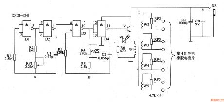
The circuit consists of OSC A, OSC B and step-up circuit. (It is showed in picture 9-37.)
OSC A is used to produce signal of low frequency to control OSC B. change the value of RP1 to change the rate of the signal of low frequency.
OSC B is under the control of OSC A. It can produce pulse signal string of low frequency. The signal is amplified and changed by the step-up circuit. It produces pulse voltage of low frequency on W2-W5. The voltage is adjusted by RP2-RP5. Then it is added on the proper part of body by poles.
(View)
View full Circuit Diagram | Comments | Reading(517)
Charger for Motor Vehicle Storage Battery (the 4th)
Published:2011/6/26 9:18:00 Author:Felicity | Keyword: Charger for Motor Vehicle Storage Battery (the 4th)
Work of the circuit
The circuit consists of main charging circuit and controlling circuit. (It is showed in picture 7-149.)
Turn on the power switch S1. 220V AC voltage is reduced by T1. S2 is the transforming switch of the charging output. The ammeter PA has two measuring ranges. One is 0-30A which shows the current of low-capacity battery. While the other one is 0-20A which shows the current of high-capacity battery. The controlling circuit can produce trigger pulse to control the charging current of the charger.
Change the value of RP to change the outputting current of the charger. Make sure that RP’s value is on the top before you start.
(View)
View full Circuit Diagram | Comments | Reading(799)
Charger for Motor Vehicle Storage Battery (the 2nd)
Published:2011/6/26 8:50:00 Author:Felicity | Keyword: Charger for Motor Vehicle Storage Battery (the 2nd)
Work of the circuit
The circuit consists of charging circuit and current controlling circuit. (It is showed in picture 7-147.)
Turn on the power switch S1 and the 220V voltage is adjusted. It produces pulse AC voltage. The pulse voltage is added to the positive pole of VT. Because it is not linked to GB the OSC does not work. The voltmeter PV and ammeter PA don’t work either.
When the battery is linked the OSC starts working. The voltage is added on the controlling pole of VT. The charger starts working. When the 24V battery is charged, the switch should on position a. When the 12V battery is charged, the switch should on position b.
Change the value of RP to change the current.
(View)
View full Circuit Diagram | Comments | Reading(477)
Charger for Motor Vehicle Storage Battery (the 1st)
Published:2011/6/26 8:48:00 Author:Felicity | Keyword: Charger for Motor Vehicle Storage Battery (the 1st)
Work of the circuit
The circuit consists of resistor R1, R2, stabilization diode VS and so on. (It is showed in picture 7-146.)
The AC voltage of the farm motor is rectified by UR. It then turns into AC voltage. The voltage is put on VT1 and VT2. When the pressure of GB is too low the pulse voltage is adjusted by R1 and VS. It supplies trigger voltage to VT1 to make VT1 trigged. When VT1 is transmitted the +V voltage is adjusted by R1 and VS. And VT2 is trigged too. The +V voltage charges GB through VT2. The voltage on GB is large enough and the charging stops.
(View)
View full Circuit Diagram | Comments | Reading(451)
Piles Therapeutic Equipment (the 2nd)
Published:2011/6/28 7:59:00 Author:Felicity | Keyword: Piles Therapeutic Equipment (the 2nd)
Work of the circuit
The circuit consists of power circuit, heating circuit, indicating circuit, vibration circuit and timing circuit. (It showed in picture 9-25.)
Turn on the power switch S. the 220V voltage is reduced by T. it then produces 36V, 6.3V and 10V AC voltage. When V1 is transmitted, it exports driving voltage from the poles. The voltage is added to EH and makes EH starts heating. Change the value of RP2 to change the value of V1, outputting voltage and outputting current. In that way the heating temperature of EH is changed.
The vibration heating probe consists of vibration and EH. The internal time is 4-5s. When S is turned on, HL1 shines. When the vibration works, HL2 shines. When the vibration stops working, the HL3 shines.
(View)
View full Circuit Diagram | Comments | Reading(455)
Piles Therapeutic Equipment (the 1st)
Published:2011/6/28 7:58:00 Author:Felicity | Keyword: Piles Therapeutic Equipment (the 1st)
Work of the circuit
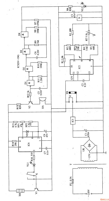
The circuit consists of power circuit, temperature controlling circuit, sound warning circuit and pulse heating circuit. (It showed in picture 9-24.)
The 220V AC voltage supplies 12V DC working voltage to the whole circuit. The low frequency OSC consists of IC4 and the other parts around. The low frequency pulse signal is outputted from pin 3 of IC4. The signal makes V 1 and EH works with pause. The range of temperature is 37-45℃. If the temperature is higher than 45℃, the high level is exported from pin 10 of IC2. The high level is adjusted and drives HA to make warning sound.
When you use the machine, put the medicine on the probe and put it into the anus. Choose the proper temperature to make it work. (View)
View full Circuit Diagram | Comments | Reading(619)
Low frequency Therapeutic Equipment (the 3rd)
Published:2011/6/28 7:50:00 Author:Felicity | Keyword: Low frequency Therapeutic Equipment (the 3rd)
Work of the circuit
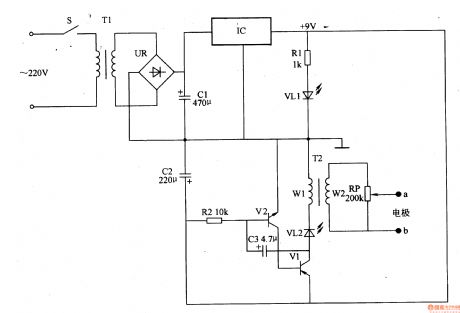
The circuit consists of power circuit IC and pulse pressure producing circuit. (It is showed in picture 9-21.)
Turn on the power switch. The 220V AC voltage is adjusted. It then separates into two parts. One supplies 9V DC voltage to the pulse pressure producing circuit. And the other is limited by R1 and lightens VL1.
The low frequency OSC works and VL2 shines. And winding W2 of T2 produces pulse pressure. The pressure is adjusted by RP and added to the acupoints. It gives some assisting treatment to some chronic diseases. (View)
View full Circuit Diagram | Comments | Reading(787)
Low frequency Therapeutic Equipment (the 2nd)
Published:2011/6/28 7:51:00 Author:Felicity | Keyword: Low frequency Therapeutic Equipment (the 2nd)
Work of the circuit
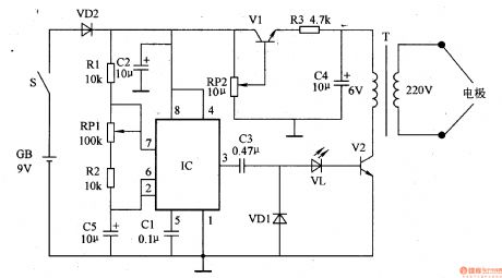
The circuit consists of time based integrated circuit IC, transistor V1, V2 and pulse transformer T. (It is showed in picture 9-20.)
Turn on the power switch S and the OSC begins to work. Pin 3 of IC produces pulse signal of low frequency. This signal makes V2 working. Then the pressure is transmitted to muscular tissue or acupoints. It relaxes or stimulates acupoints to give some assisting treatment to some chronic diseases.
(View)
View full Circuit Diagram | Comments | Reading(1157)
| Pages:1657/2234 At 2016411642164316441645164616471648164916501651165216531654165516561657165816591660Under 20 |
Circuit Categories
power supply circuit
Amplifier Circuit
Basic Circuit
LED and Light Circuit
Sensor Circuit
Signal Processing
Electrical Equipment Circuit
Control Circuit
Remote Control Circuit
A/D-D/A Converter Circuit
Audio Circuit
Measuring and Test Circuit
Communication Circuit
Computer-Related Circuit
555 Circuit
Automotive Circuit
Repairing Circuit