Alarm Control
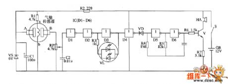
Gas leak alarm circuit diagram
Published:2011/6/13 5:04:00 Author:Lucas | Keyword: Gas leak alarm | From:SeekIC

The gas leak alarm circuit is composed of the power supply circuit, gas detection circuit, LED indicating circuit and sound alarm circuit, and the circuit is shown as the chart. Power supply circuit is composed of the battery CB, power switch s, current limiting resistor R2, zener diode VS and filter capacitor C1. Gas detection circuit consists of the gas sensor, resistors R1 and potentiometer RP. LED indicating circuit consists of the NOT gates D1~D2 which are inside of NOT gate integrated circuit IC1(D1~D6), resistor R3, capacitor C2, and two-color light-emitting diodes VL. Sound alarm circuit is composed of the diode VD, NOT gates D4~D6 which are inside of IC, resistors R4 ~ R7, capacitor C3, transistor V, and buzzer HA. R2 uses 1/2W metal film resistor.
Reprinted Url Of This Article:
http://www.seekic.com/circuit_diagram/Control_Circuit/Alarm_Control/Gas_leak_alarm_circuit_diagram.html
Print this Page | Comments | Reading(3)

Article Categories
power supply circuit
Amplifier Circuit
Basic Circuit
LED and Light Circuit
Sensor Circuit
Signal Processing
Electrical Equipment Circuit
Control Circuit
Remote Control Circuit
A/D-D/A Converter Circuit
Audio Circuit
Measuring and Test Circuit
Communication Circuit
Computer-Related Circuit
555 Circuit
Automotive Circuit
Repairing Circuit
Code: