Signal Processing
Heart Rhythm Tester (the 4th)
Published:2011/6/23 21:40:00 Author:Felicity | Keyword: Heart Rhythm Tester (the 4th) | From:SeekIC

Work of the circuit
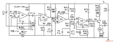
The circuit consists of photo electricity testing circuit, signal amplifying circuit, buzzer driving circuit and current indicating circuit. (It is shows in picture 9-56.)
When you do the test, put your finger between EL and RG. Some lights of EL go through the finger and shines on RG. RG produces sensitive signal. The signal is amplified by N1-N3 and separates into two parts. One drive HA makes the buzzer work. And the other one goes through ammeter and indicates the current value. The current value increases by the rate of heart beating.
Change the value of RP1 to change the accuracy. Change the value of RP2 to change the testing scope.
Reprinted Url Of This Article:
http://www.seekic.com/circuit_diagram/Signal_Processing/Heart_Rhythm_Tester_the_4th.html
Print this Page | Comments | Reading(3)

Article Categories
power supply circuit
Amplifier Circuit
Basic Circuit
LED and Light Circuit
Sensor Circuit
Signal Processing
Electrical Equipment Circuit
Control Circuit
Remote Control Circuit
A/D-D/A Converter Circuit
Audio Circuit
Measuring and Test Circuit
Communication Circuit
Computer-Related Circuit
555 Circuit
Automotive Circuit
Repairing Circuit
Code: