Signal Processing
Electric Medical Attracting Controlling Circuit (the 3rd)
Published:2011/6/25 5:22:00 Author:Felicity | Keyword: Electric Medical Attracting Controlling Circuit (the 3rd) | From:SeekIC

Work of the circuit
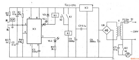
The circuit consists of power circuit, negative pressure testing circuit, bistable state circuit, VL indicating circuit and controlling execution circuit. (It is showed in picture 9-45.)
Turn on the power switch S2. The 220V AC voltage supplies +12V working power to bistable state circuit and controlling execution circuit.
When the circuit just starts working, the gas in the negative pressure bottle is of normal state. The internal outputting circuit of KP is closed and VL1 is lightened. At the same time, M starts working normally. When the negative pressure reaches to a certain value, M stops working. At the same time VL2 is lightened and VL1 is turned off. When the negative pressure is lower than a certain value, M starts working immediately.
S2 is the manual button. Press S1 and M starts working. Relax S2 and M stops working.
Reprinted Url Of This Article:
http://www.seekic.com/circuit_diagram/Signal_Processing/Electric_Medical_Attracting_Controlling_Circuit_the_3rd.html
Print this Page | Comments | Reading(3)

Article Categories
power supply circuit
Amplifier Circuit
Basic Circuit
LED and Light Circuit
Sensor Circuit
Signal Processing
Electrical Equipment Circuit
Control Circuit
Remote Control Circuit
A/D-D/A Converter Circuit
Audio Circuit
Measuring and Test Circuit
Communication Circuit
Computer-Related Circuit
555 Circuit
Automotive Circuit
Repairing Circuit
Code: